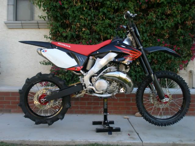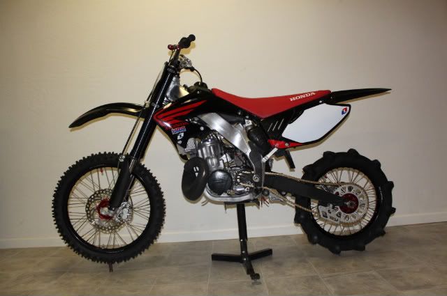
I did not do enough research on the 125 vs 250 conversions. I had seen some smoking deals on 125s in the phoenix area, so I bought a billet wye, and head stays for gen 3 125 on ebay. I have not seen a smoking deal on a 125 since! I ended up getting a frame only for now.
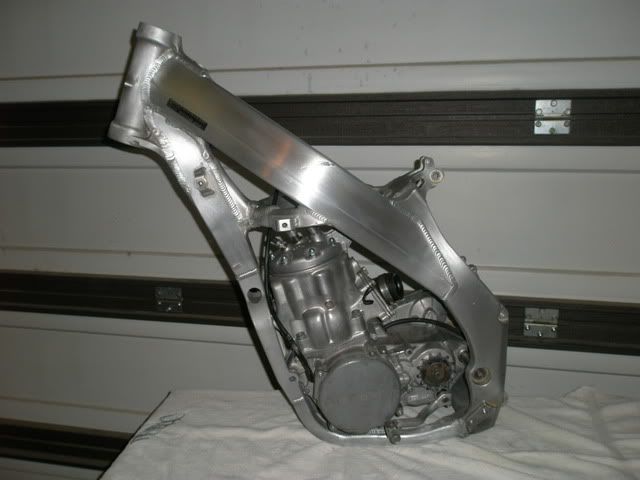
Hind sight being 20/20, I have decided I would be better served had I done a 250 conversion “Algava Style”
http://cr500riders.com/cgi/yabb/YaBB.pl ... 913934/0#0
I think the "algava" 250 is the cleanest, most straight forward way to do it. I would eliminate the 125 pipe / tire contact problem, and the rake angle is probably better for the riding I do, dunes.
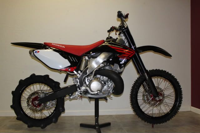
There are some cool things about the 125 though.
On the earlier years, probably ’02 – ’03, the left hand spar does is a lot cleaner than the 250. It does not have the brackets on the left spar for the power valve the way the 250 does. The handling should be quite nimble. It comes stock with the correct swing arm spacers, and lets face it to the average Joe telling them I put a 500 engine in a 125 will seem way cooler.
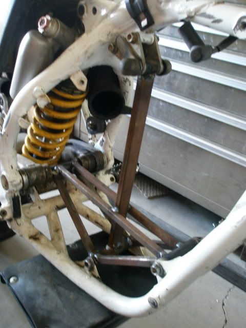
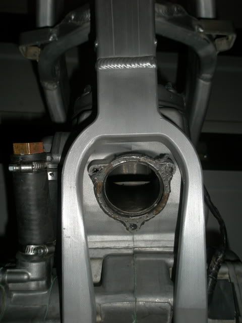
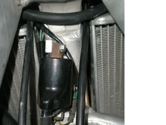
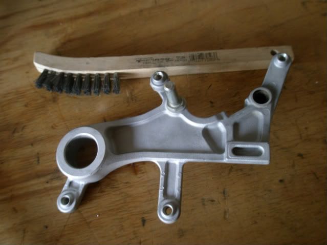
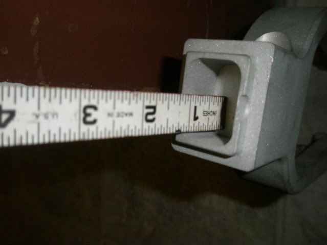
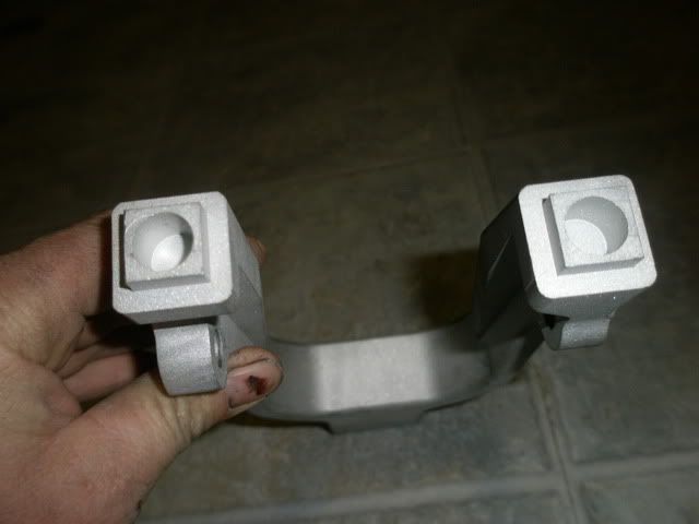
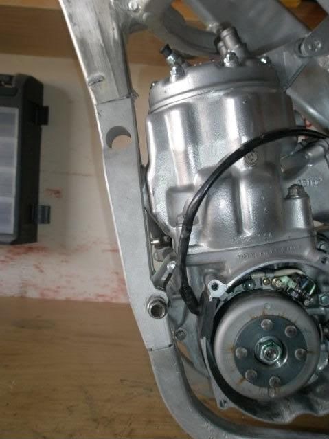
The wye that I got is very nice. It has built in front mounts and it really hugs close to the engine, allowing max space for the pipe.
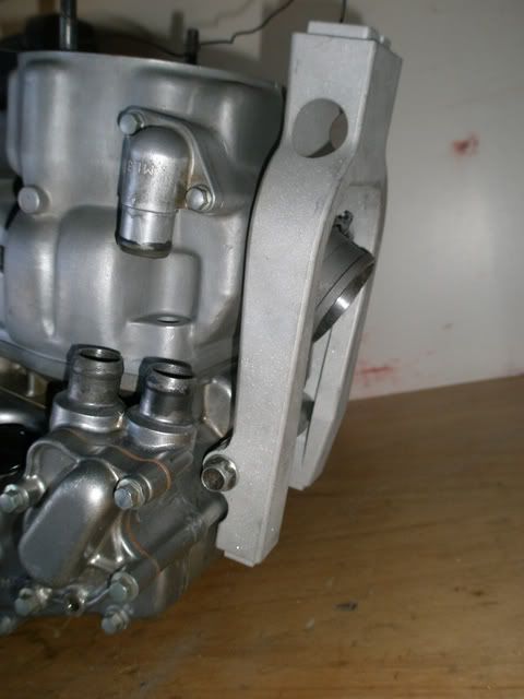
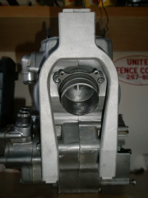
Although the kit came with a steel model by which to have new lower tubes bent, I decided to try to keep the original tubes. I used AF’s post as reference.
http://cr500riders.com/cgi/yabb/YaBB.pl?num=1104642490
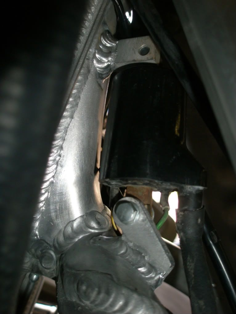
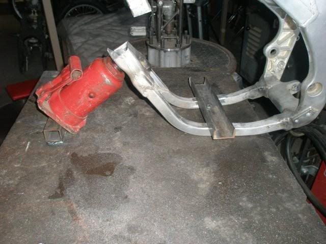
I removed the front mounts, and I cut the top welds on the oem wye. I followed the techniques I read in other posts, patience is key. Go slow and keep an eye on the entire radius of the cut off wheel. If you are looking only at the blade and where you want to cut, elsewhere on the blade it may be cutting somewhere you do not want. For this conversion I would have been well off to have just cut the down tube just above the oem wye with a portable band saw, I did the careful removal as practice. I would also have been well off to have removed the lower mounts, and the coil mounts at this point.
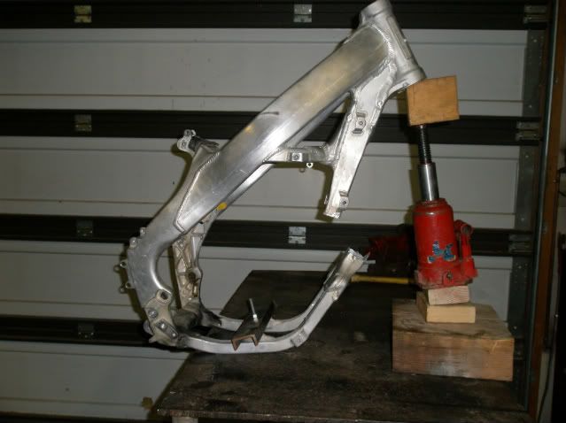
Next I set about to take some of the bend out of the oem cradle down by the pegs. I left the oem wye in tact to help keep both sides bending at the same rate. In AFs post he said he used a press, and it took 5 tons of force to bend. I am assuming he was bending each tube individually. I decided to try to take some temper out of the tube before bending.
One time I needed to bend a piece of aluminum tread plate as a rock guard for the front of a trailer. The tread plate was tempered and hard to bend. A friend taught me to light a rose bud with acetylene only and spread soot all over the tread plate, then to turn the oxy on and get a good flame and heat the piece until the soot burned off, let the piece return to room temp on its own and then bend. Once bent some of the temper returned. The soot / burn off is just an indicator of temperature. You must keep the torch moving fast as not to burn through in one spot.
I used this technique on the lower bend by the pegs. I am not sure what effect it had. I could not bend by hand. I had to bolt the frame to my welding bench and use a jack to bend. It seemed to bend very easy. I did not even use a handle in the jack.
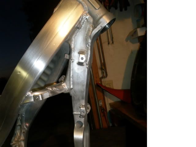
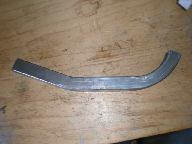
I bent little by little test fitting the engine after each bend. I was hoping that when I got to the right bend the lower mounts would magically be in the correct location. I was able to get the lower mounts to line up, and get both the swing arm bolt and lower mount bolt in, but the nose was too far up. The kick starter did not fit in the frame, nor the head stay. I ended up removing the lower mounts. I will either reuse them located about ½” back or use the front mounts that I removed. My preference is the front mounts they are slightly shorter so the frame would hug better, but I may have bent the frame too much to use them.
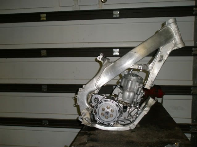
All the broken bikes that have broken in half that I have seen have been billet wye bikes, most likely due to the billet being so thick and not heating enough to get good penetration. This wye has milled pockets that should help out. I also plan on pre heating a bit.
I did some work bending the front of the tubes. I left the oem wye intact for a more uniform bend. I used the same soot it up and burn it off procedure detailed above. I was in a hurry trying to squeeze it in before guests showed up for my 8 yr. old’s birthday party, and I broke the #1 rule, patience, and over bent a bit. The left hand tube turned out nice. There is a lot of room on that side, also the LH down tube form the wye is about a ½” further back. The right hand side is a tight fit, and by just continuing the oem bend, it kicked the tube into the water pump. Hind sight I should have cut the wye before bending the front tubes and bent them independent. I should have just continued the oem bend on the left side (as I did), but for the right side I should have used the cut a pie shaped piece out and bent as detailed in AF’s build, or as Jercs recommended. I also had to tighten up the spread between the tubes as the connection to the billet wye is a little tighter.
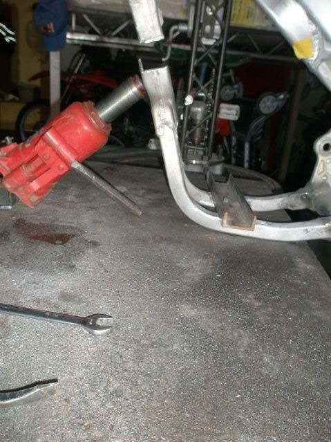
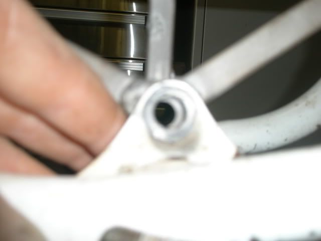
Getting a little closer, I need to cut about another 1/8” to ¼” off the down tube to raise the wye to rotate the engine up so it fits the head stay.
Any recommendations on a welder in the phoenix area? I have access to a very nice TIG, but do not feel comfortable welding aluminum.