Before I started the metamorphosis of the cr250 I am thinking to myself, "How can I just tear apart a perfectly good 250?" Then miraculously, a hilarious thought, maybe on the brink of a hoon motto, would lighten my soul and take away all doubt.
"A 250 is just 250 too small"
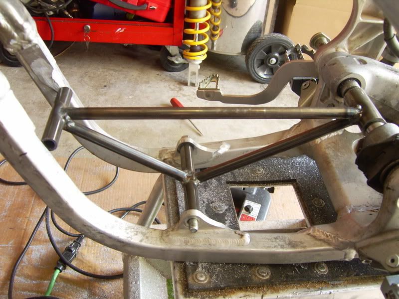
Here are some pics of the project thus far. Pardon the blurry ones. My camera freaks out with low lighting.
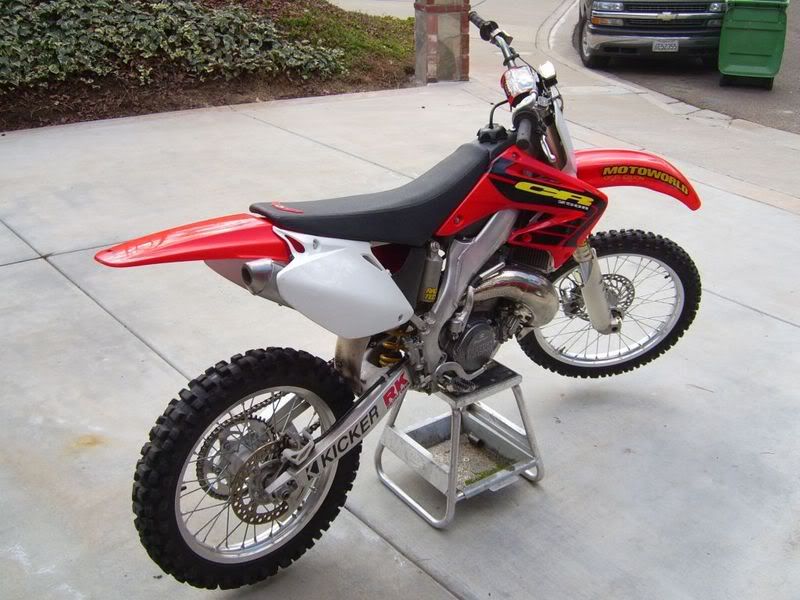
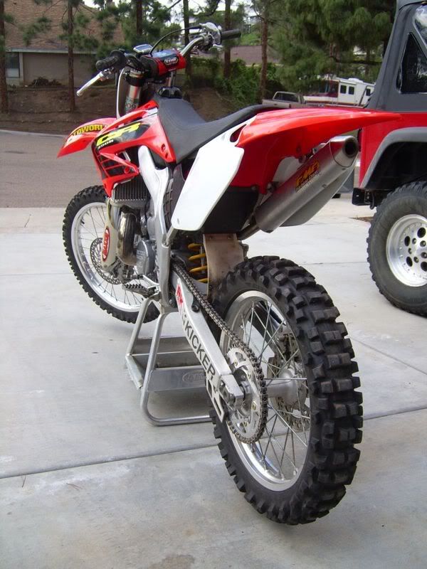
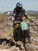
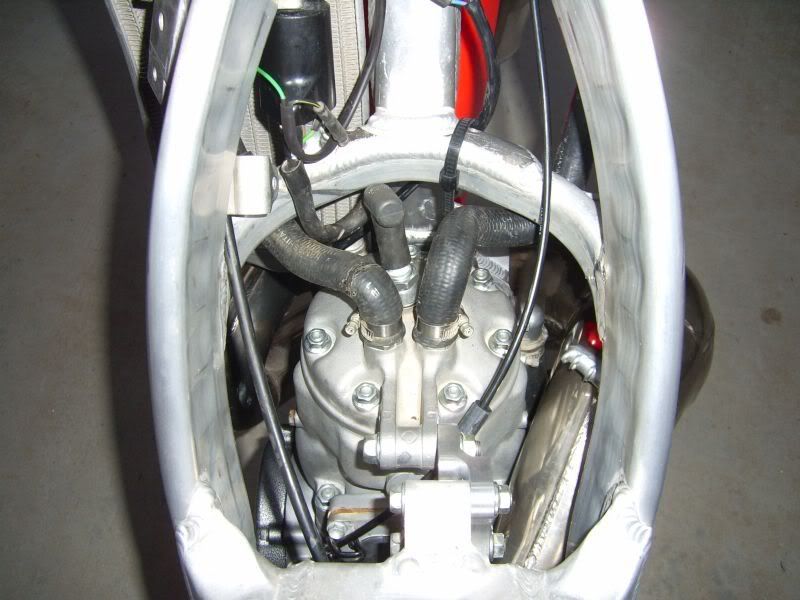
The steed before the speed...
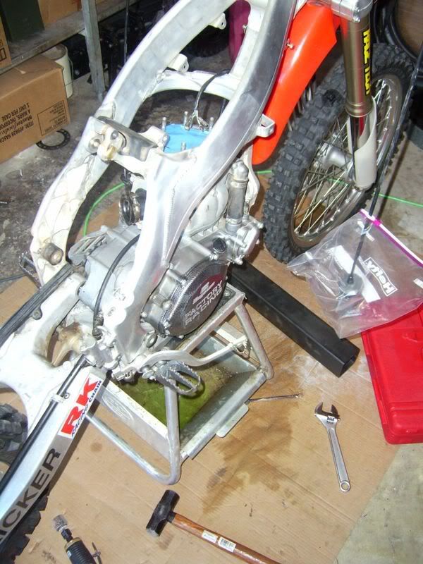
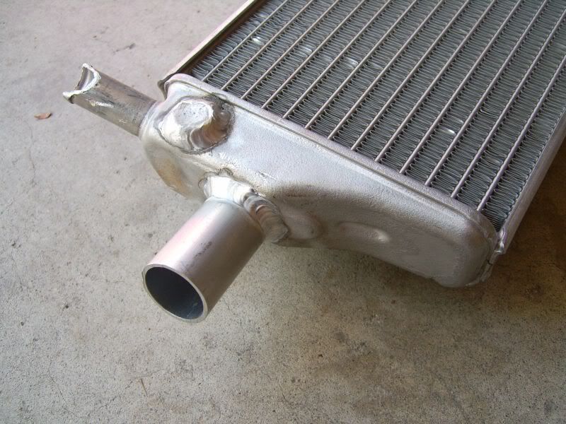
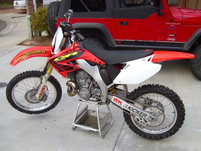
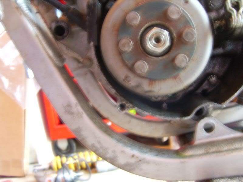
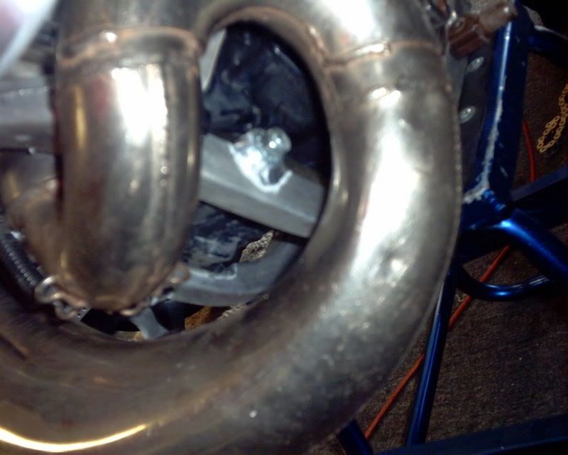
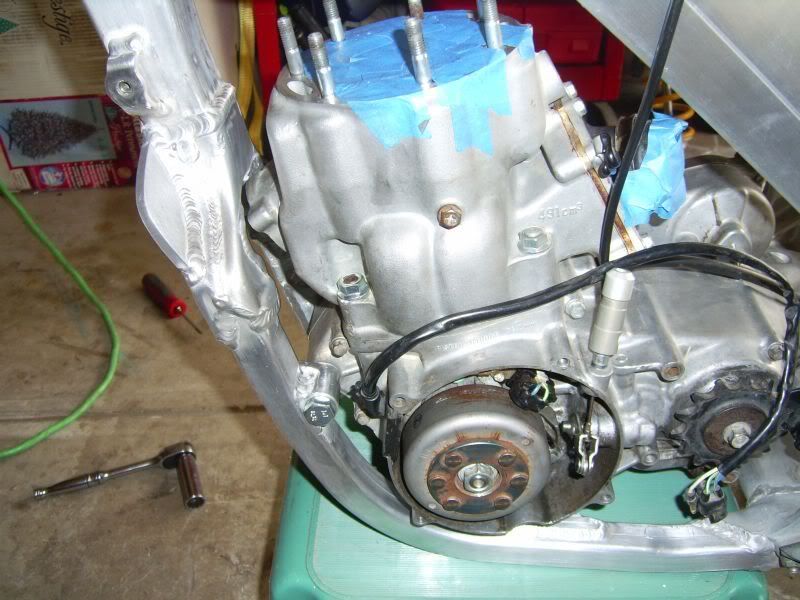
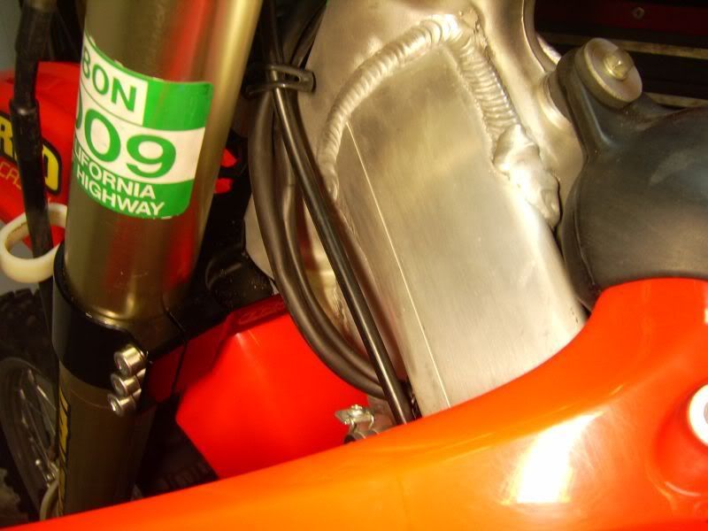
Oh whats that, a 5 hundy in there?!
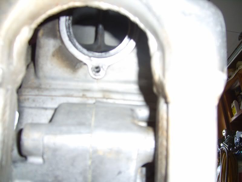
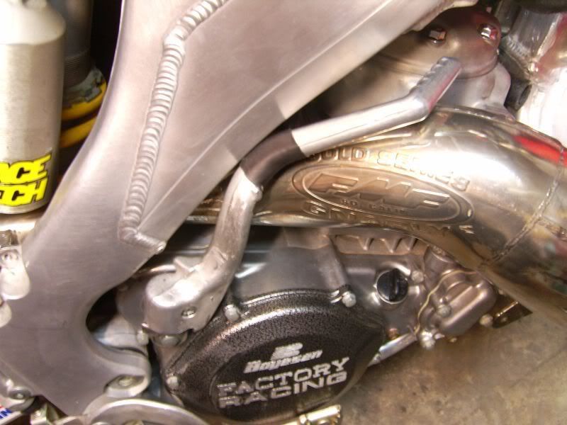
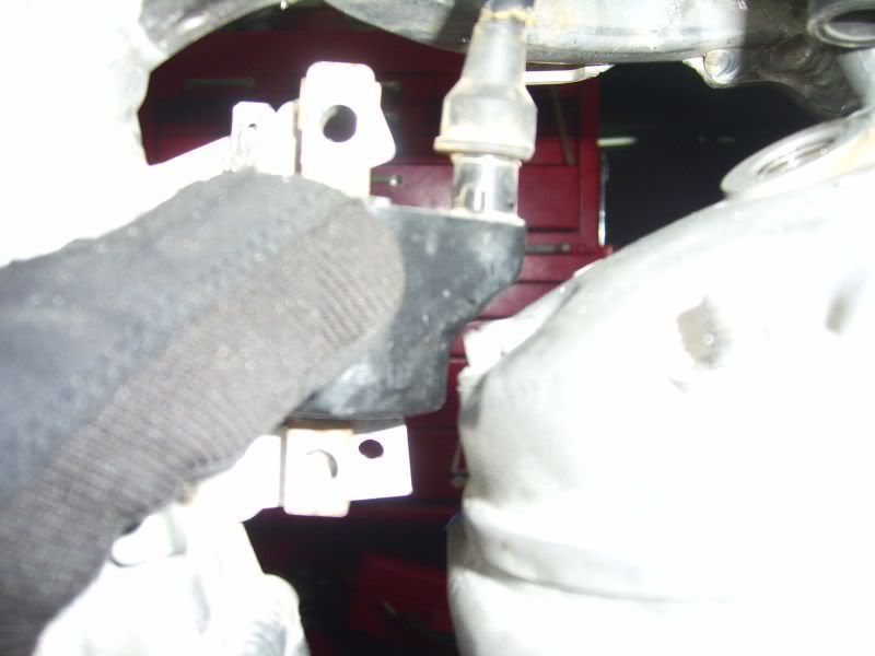
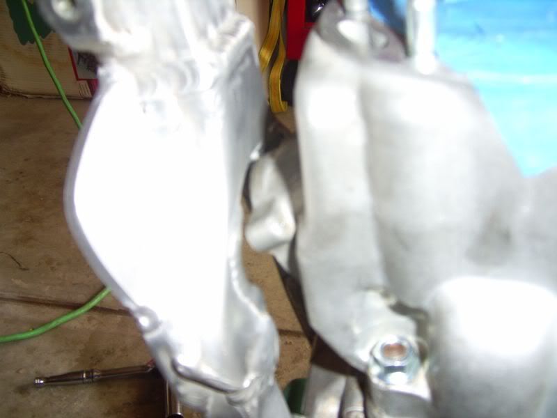
The motor looks like it hangs to more of the left side.
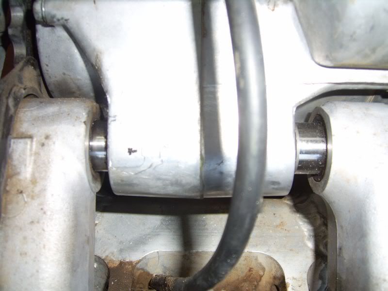
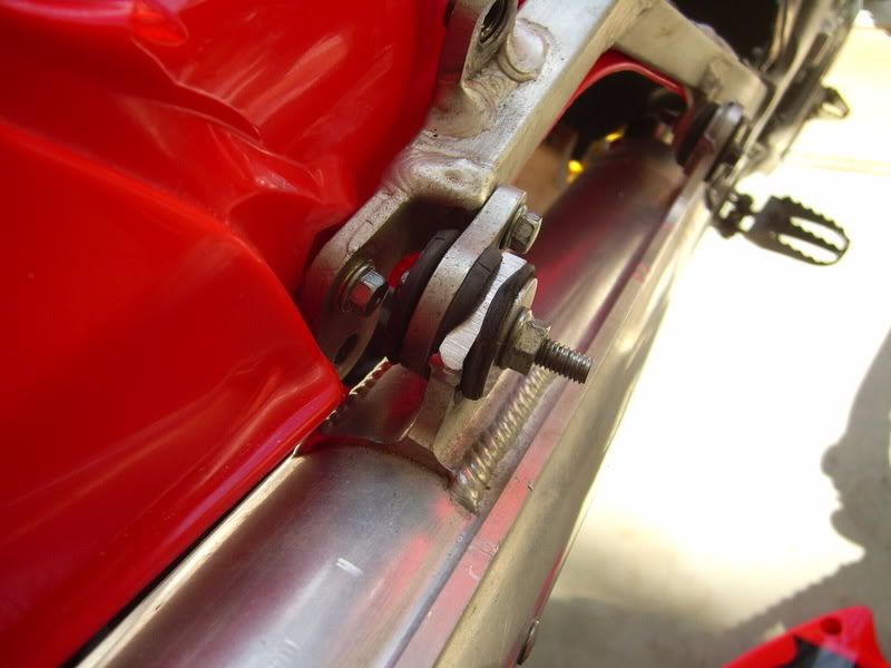
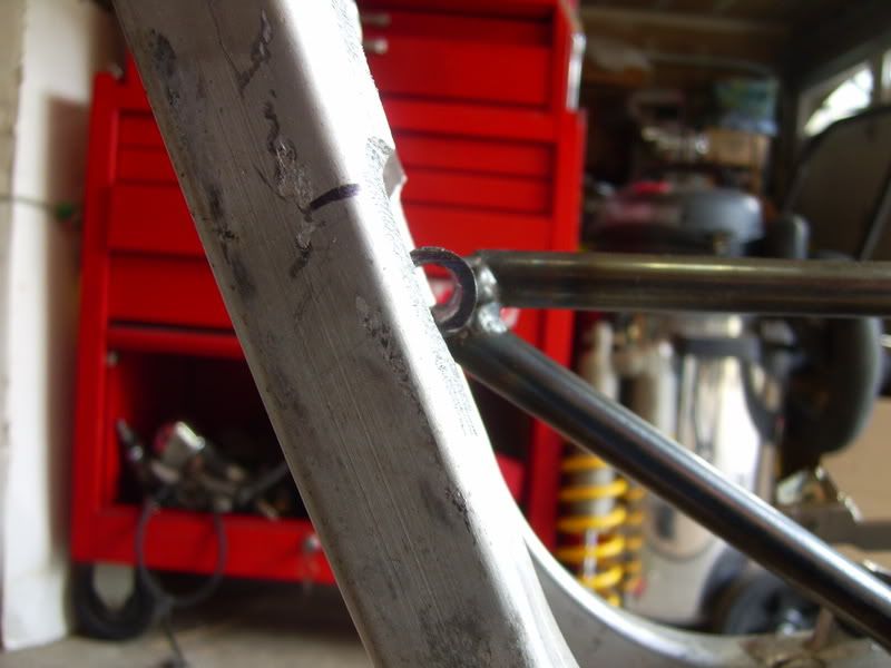
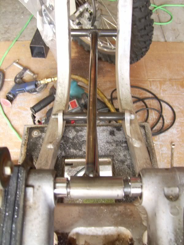
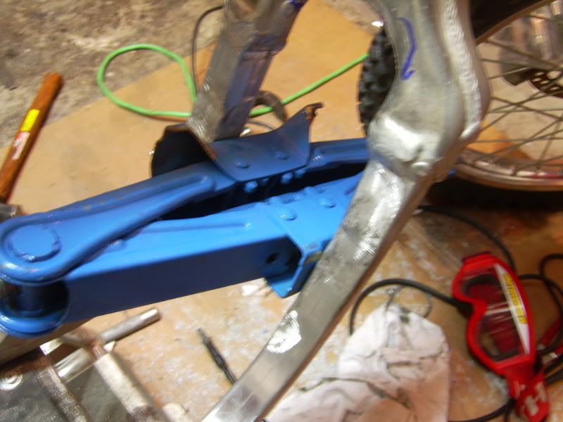
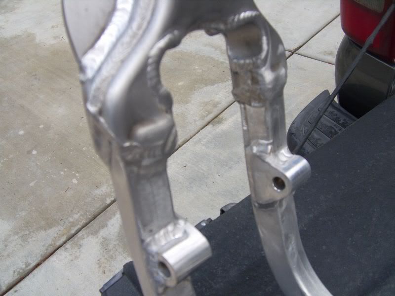
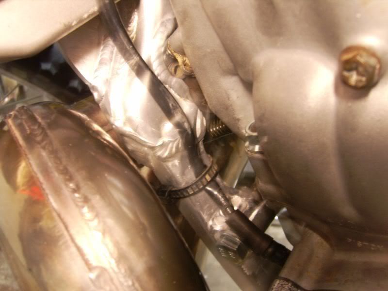
CR125 spacers...
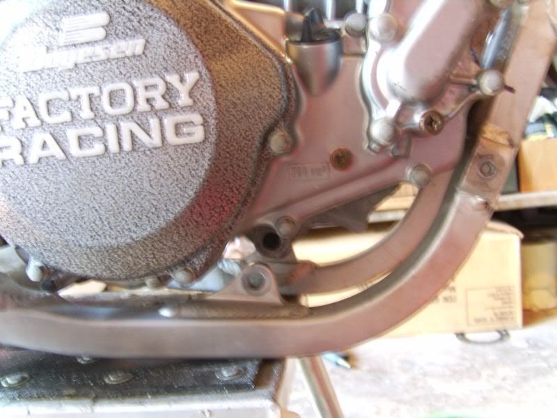
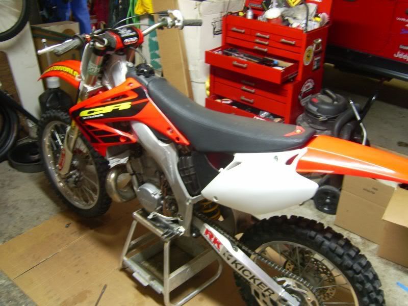
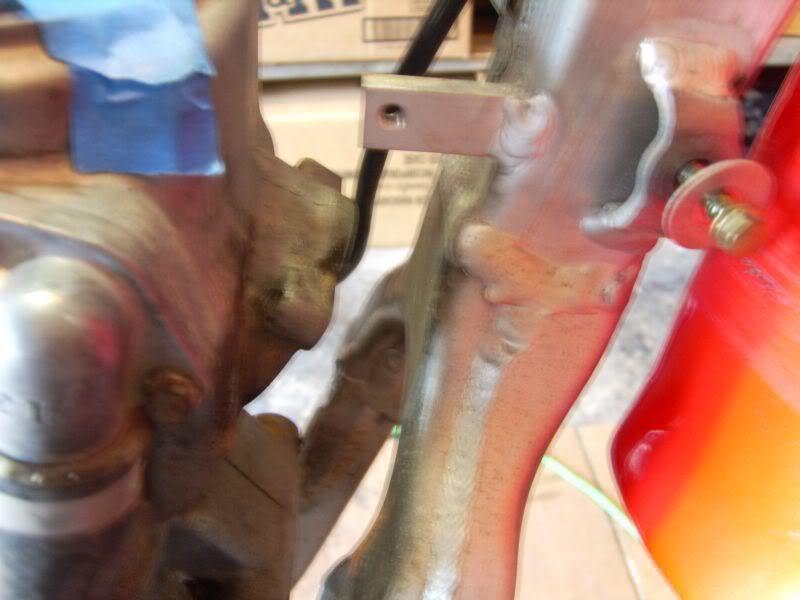
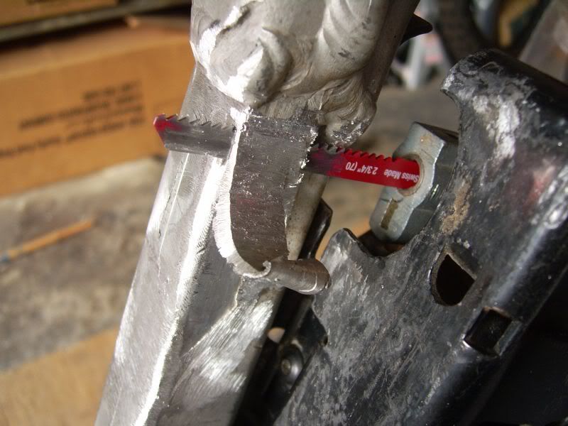
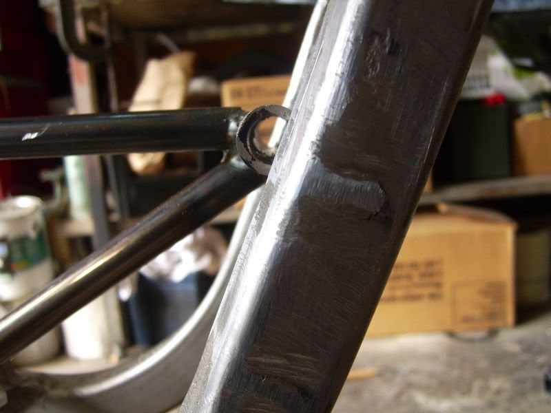
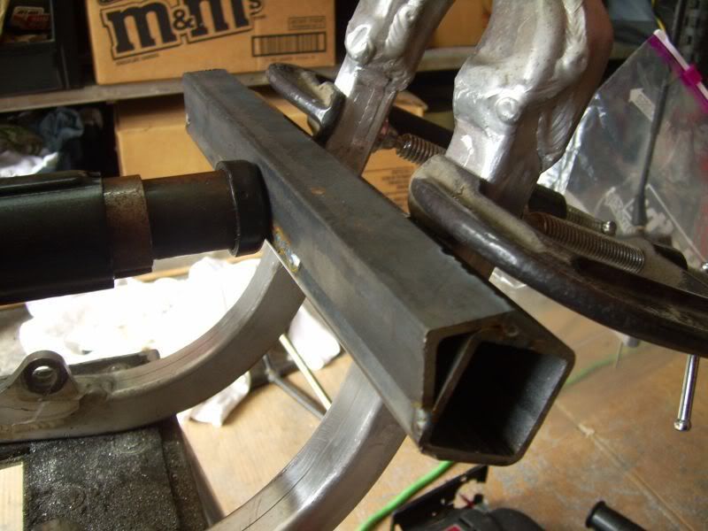
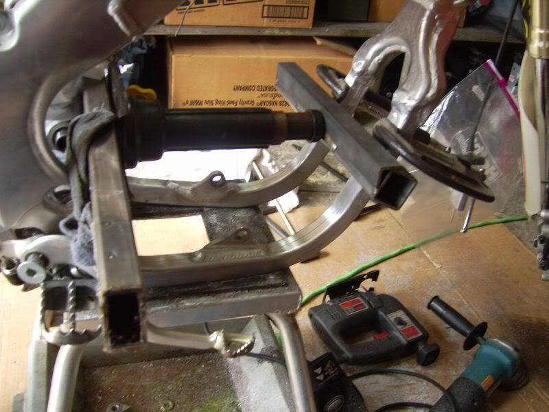
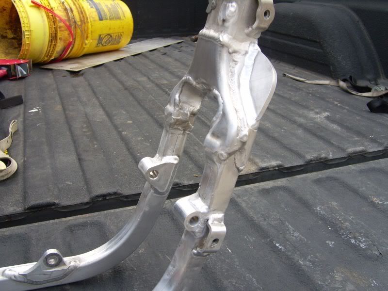
More prep work to do. Shan, I need the headstay and front mounts post haste!


 "the game of life of is not so much in holding a good hand as playing a poor hand well"