Forward:
When I first did this How-To I meant for it to be used by anyone who needed added explanation. Some time has passed, and I have some new idea's that I would like to incorporate. I do not wish for this to be locked down. I believe that it should be available to anyone in need.....then it will truly serve its intended purpose.
Disclaimer:
Use of this thread shall be done at your own risk. Please know the health risk's involved with handling Gas, Cleaning Solvents, Greases, Coolant, Oil ect. Be familiar with MSDS's** and wear proper PPE (Personal Protective Equip). I will not except responsibility for scribes stuck in eyeballs, kids drinking coolant, radioactive cats, house catching on fire, busted cases or any damage to your bike or person....etc. I used the correct tools for the job unless otherwise stated. If you have difficulty with tools or are not mechanically inclined....have a professional do the work for you. Please use your Honda Service Manual!!!! Onward......
** MSDS--Material Safety Data Sheets: http://en.wikipedia.org/wiki/Material_safety_data_sheet
MSDS Examples:
Chem-Tool:
http://www.berrymanproducts.com/Default.aspx?tabid=120
Maxima 927:
http://www.maximausa.com/technical/MSDS ... %20927.pdf
Motor Overhaul Pictorial
-
Rosco-Peeko

- Posts: 823
- Joined: June 1st, 2007, 2:47 pm
Motor Overhaul Pictorial
Last edited by Rosco-Peeko on March 31st, 2010, 5:50 am, edited 6 times in total.
Somewhere in Kenya, a village is missing their idiot.......
-
Rosco-Peeko
- Posts: 823
- Joined: June 1st, 2007, 2:47 pm
Part I Prep
Prep:
What do I need?
1) 1 each Honda Service Manual for YOUR bike
2) An assortment of Combination Wrenches 6mm-22mm (preferred or
6-14MM bare minimum.)
3) Metric Socket Set 6mm-32mm Shallow, 6mm-14mm Deep
4) Ratchet's 1/4, 3/8 and or 1/2 drive
5) 1/2 drive Breaker Bar
6) Various extensions 3", 6" and 12"...drive or your choice...1/4 is
probably the best due to being skinny.
7) Screwdriver Set, slotted and standard in various sizes
8. The "All 16ths" = Big freaking Crescent or Ford Wrench
9) Various reducers or adapters i.e. 1/4 dr to 3/8 dr...ect
10) Metric Feeler Gauges
11) The Persuader = 10 LBS Dead-Blow Soft Face Mallet
12) Shop Rags
Optional/nice to have tools:
1) Scribe set
2) Set of Punches...brass preferably
3) Speed Handle....gotta love it....10x faster than a ratchet!
4) Plug Wrench
5) Bernzomatic Propane torch
6) Steering wheel puller (Craftsman)
7) Spackle Knife
Special Tools needed:
1) Doing this shit right? Torque Wrench!!!!
http://www.craftsman.com:80/shc/s/searc ... h&sLevel=0
2) Torque adapter for head and cylinder nuts (Motion-Pro)
http://www.motionpro.com/motorcycle/partno/08-0134/
3) Vainer Caliper or Outside Micrometer
http://www.harborfreight.com/cpi/ctaf/d ... mber=47256
4) "The Grabbit" Clutch Basket/Sprocket Holder Tool (Motion-Pro)
http://www.motionpro.com/motorcycle/partno/08-0008/
5) Flywheel puller
http://www.motionpro.com/motorcycle/partno/08-0026/
6) Two plain jane pennies
Consumables:
1) Fresh Premix of your choosing
2) Tranny Oil of Choice
3) Zip-ties...various sizes
4) New Seals, Crush Washers and Gaskets
5) Masking Tape
6) Zip-Lock bags...a bunch....bag all of your stuff up by section and
mark bags with a sharpie on contents.
A) Why? It makes build up faster...because all of your crap is in
one place and easy to find
B) Lessens the chance of loosing stuff that you do not want to
lose.
C) Keeps contaminants off your stuff. "Sheesh Rob!" "Its a
dirt bike." Dirt and contaminants are the
#1 bearing killer...look it up! Throw
away your hard earned money before you start.... Dont be a
Cheap-Charlie...buy some freaking bags....
7) Gasgacinch or alike gasket sealer if thats your thing...
8. Ultimate Black RTV
9) Green Scrub Pad.....new one without food on it.
10) Dielectric Grease
11) Chem-Tool B12 (the shit!) fantastic cleaner...eats paint too..careful!
12) Black or blue fine tip sharpie
13) Blue Threadlocker
14) Nitrile Gloves (latex)
15) Beer of your choice and some classic rock....lets do this!
A note about oils...coolant and the likes. Please be responsible enough to put all used fluids in a suitable container away from kids and animals. Dispose of it IAW with your State EPA/Hazmat regulations....
General Tech
Torque conversions:
There is 12 In-Lbs per every 1 Ft-Lbs and 1.35582 Nm (newton meters) per 1 Ft-Lbs
Applying toque when using an adapter (Important!!!!!)
http://www.cncexpo.com/TorqueAdapter.aspx
Types of Torque Wrenches, Beam Style (simplicity at its best and accurate) and the Break-Away/Clicker:
http://home.jtan.com/~joe/KIAT/kiat_3.htm
The importance of torquing bolts/fasteners:
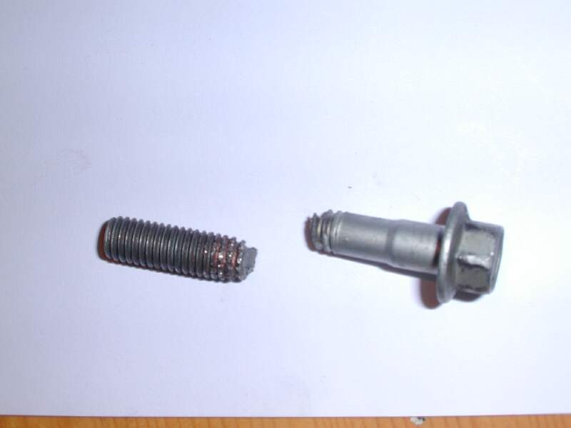
1) Over-torqueing or German Gooden-tite messes thing up. Not you are over stressing the bolts or internal threads. Bolts and nuts are rated at specific torques for a reason. Liberate threads from your cases and you're one sorry sucka.
This bolt was slightly over torqued.....wanna bet when it will fail? Pushing your bike back to the truck?

Under Torquing/too loose:
1) Simply, things have more slack to move around and wear at an accelerated rate. Or they will just fall out on the trail and possibly leave you stranded.
To achieve proper torque, your threads should be clean and lubricated.
All threads on the CR500 are right handed--Righty/Tighty, Lefty/Loosey.
Heat causes metal to expand and Cold (freezing) causes metal to contract
Corrosion and what it means to you:
http://en.wikipedia.org/wiki/Corrosion
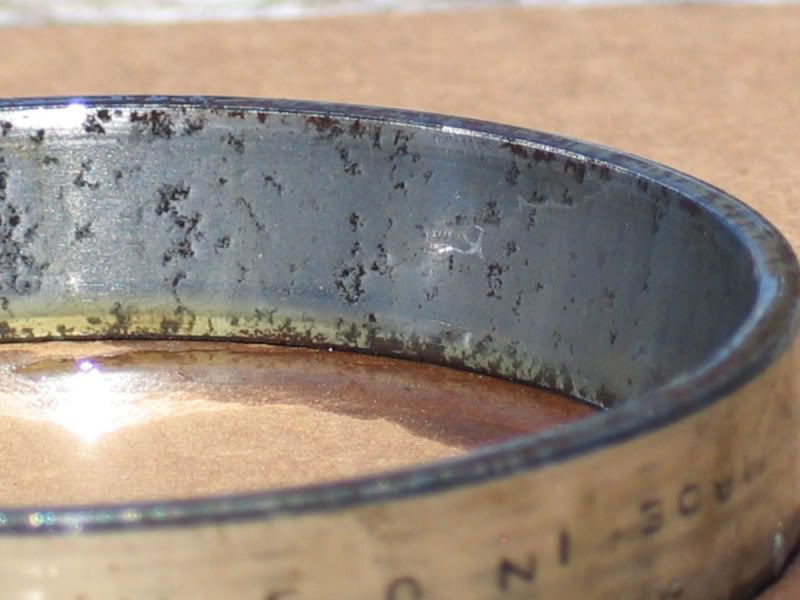
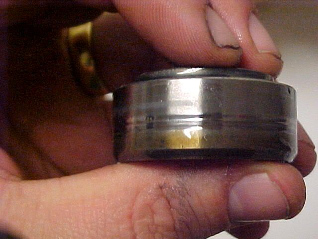
Besides straight up rust/corrosion, you will see pitting on your 500. If you have any parts that show signs of corrosion pitting; replace it! This bearing outer race it done!
Use of easy-outs:
http://www.ehow.com/how_5127433_use-easy-outs.html
http://www.craftsman.com/shc/s/p_10155_ ... =extractor
Use of Tap and Die's:
http://www.diynetwork.com/how-to/how-to ... index.html
You can also use a nut in vise, take a swiss file and cut 4 evenly spaced slots along the threads for a homemade die if in a pinch. You can do the same with a bolt.
What do I need?
1) 1 each Honda Service Manual for YOUR bike
2) An assortment of Combination Wrenches 6mm-22mm (preferred or
6-14MM bare minimum.)
3) Metric Socket Set 6mm-32mm Shallow, 6mm-14mm Deep
4) Ratchet's 1/4, 3/8 and or 1/2 drive
5) 1/2 drive Breaker Bar
6) Various extensions 3", 6" and 12"...drive or your choice...1/4 is
probably the best due to being skinny.
7) Screwdriver Set, slotted and standard in various sizes
8. The "All 16ths" = Big freaking Crescent or Ford Wrench
9) Various reducers or adapters i.e. 1/4 dr to 3/8 dr...ect
10) Metric Feeler Gauges
11) The Persuader = 10 LBS Dead-Blow Soft Face Mallet
12) Shop Rags
Optional/nice to have tools:
1) Scribe set
2) Set of Punches...brass preferably
3) Speed Handle....gotta love it....10x faster than a ratchet!
4) Plug Wrench
5) Bernzomatic Propane torch
6) Steering wheel puller (Craftsman)
7) Spackle Knife
Special Tools needed:
1) Doing this shit right? Torque Wrench!!!!
http://www.craftsman.com:80/shc/s/searc ... h&sLevel=0
2) Torque adapter for head and cylinder nuts (Motion-Pro)
http://www.motionpro.com/motorcycle/partno/08-0134/
3) Vainer Caliper or Outside Micrometer
http://www.harborfreight.com/cpi/ctaf/d ... mber=47256
4) "The Grabbit" Clutch Basket/Sprocket Holder Tool (Motion-Pro)
http://www.motionpro.com/motorcycle/partno/08-0008/
5) Flywheel puller
http://www.motionpro.com/motorcycle/partno/08-0026/
6) Two plain jane pennies
Consumables:
1) Fresh Premix of your choosing
2) Tranny Oil of Choice
3) Zip-ties...various sizes
4) New Seals, Crush Washers and Gaskets
5) Masking Tape
6) Zip-Lock bags...a bunch....bag all of your stuff up by section and
mark bags with a sharpie on contents.
A) Why? It makes build up faster...because all of your crap is in
one place and easy to find
B) Lessens the chance of loosing stuff that you do not want to
lose.
C) Keeps contaminants off your stuff. "Sheesh Rob!" "Its a
dirt bike." Dirt and contaminants are the
#1 bearing killer...look it up! Throw
away your hard earned money before you start.... Dont be a
Cheap-Charlie...buy some freaking bags....
7) Gasgacinch or alike gasket sealer if thats your thing...
8. Ultimate Black RTV
9) Green Scrub Pad.....new one without food on it.
10) Dielectric Grease
11) Chem-Tool B12 (the shit!) fantastic cleaner...eats paint too..careful!
12) Black or blue fine tip sharpie
13) Blue Threadlocker
14) Nitrile Gloves (latex)
15) Beer of your choice and some classic rock....lets do this!
A note about oils...coolant and the likes. Please be responsible enough to put all used fluids in a suitable container away from kids and animals. Dispose of it IAW with your State EPA/Hazmat regulations....
General Tech
Torque conversions:
There is 12 In-Lbs per every 1 Ft-Lbs and 1.35582 Nm (newton meters) per 1 Ft-Lbs
Applying toque when using an adapter (Important!!!!!)
http://www.cncexpo.com/TorqueAdapter.aspx
Types of Torque Wrenches, Beam Style (simplicity at its best and accurate) and the Break-Away/Clicker:
http://home.jtan.com/~joe/KIAT/kiat_3.htm
The importance of torquing bolts/fasteners:
1) Over-torqueing or German Gooden-tite messes thing up. Not you are over stressing the bolts or internal threads. Bolts and nuts are rated at specific torques for a reason. Liberate threads from your cases and you're one sorry sucka.
This bolt was slightly over torqued.....wanna bet when it will fail? Pushing your bike back to the truck?
Under Torquing/too loose:
1) Simply, things have more slack to move around and wear at an accelerated rate. Or they will just fall out on the trail and possibly leave you stranded.
To achieve proper torque, your threads should be clean and lubricated.
All threads on the CR500 are right handed--Righty/Tighty, Lefty/Loosey.
Heat causes metal to expand and Cold (freezing) causes metal to contract
Corrosion and what it means to you:
http://en.wikipedia.org/wiki/Corrosion
Besides straight up rust/corrosion, you will see pitting on your 500. If you have any parts that show signs of corrosion pitting; replace it! This bearing outer race it done!
Use of easy-outs:
http://www.ehow.com/how_5127433_use-easy-outs.html
http://www.craftsman.com/shc/s/p_10155_ ... =extractor
Use of Tap and Die's:
http://www.diynetwork.com/how-to/how-to ... index.html
You can also use a nut in vise, take a swiss file and cut 4 evenly spaced slots along the threads for a homemade die if in a pinch. You can do the same with a bolt.
Last edited by Rosco-Peeko on April 15th, 2010, 5:32 pm, edited 5 times in total.
Somewhere in Kenya, a village is missing their idiot.......
-
Rosco-Peeko
- Posts: 823
- Joined: June 1st, 2007, 2:47 pm
Part II Minor/Externals Removal
Seat Removal:
Speedhandle setup, break torque and removed two each bolts that secure seat to SubFrame/Side Panels. and slide seat aft and up away from bike.
Gas Tank Removal:
Turn Petcock "off" and disconnect Carb Fuel Line. Cap off the Fuel Line to Carb...bolt works well. Remove 2ea bolts securing Shrouds to Radiators. Next, removed 2 ea inner bolts securing Tank to Frame. Unhook band from aft side of Tank and remove tank from bike.
Drain oil from Tranny:
Please use suitable container and dispose of responsibly.
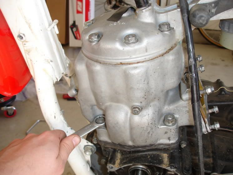
Drain Engine Coolant:
First, remove radiator cap and set off to the side. Next have a container ready....remove drain bolt off Water Pump Housing. Catch any fluid that comes out...also lean the bike over a bit to help drain the system.
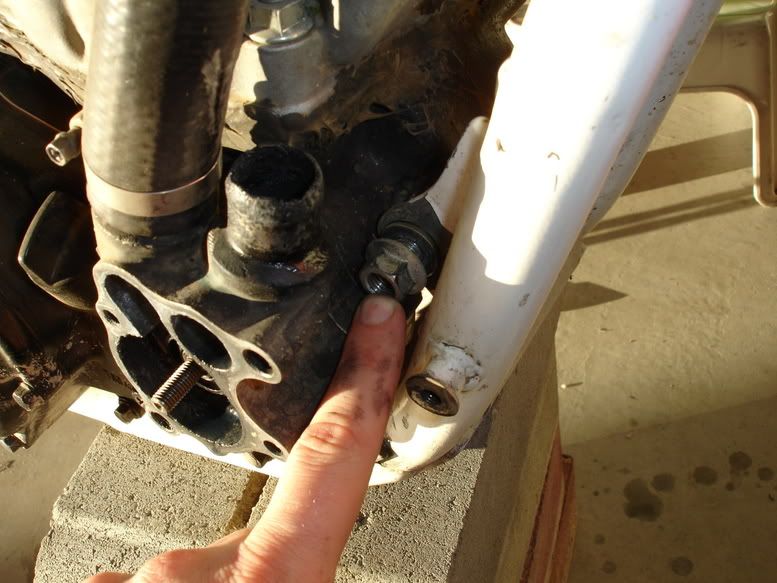
It is also a good idea to remove bolt in Cylinder and drain water jacket. Bolt right in the middle of the jug on the left side with copper crush washer. After Draining is completed, put drain bolts back in and put Radiator Cap back on.
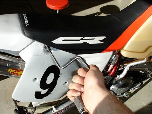
Right Side Panel Removal:
Remove 1 each bolt. After panel is removed, you can put it back into subframe for easy build up.
Silencer Removal:
Remove 2 ea bolts securing Silencer to SubFrame. Wiggle silencer out of Expansion Chamber and pull out and away from bike. You can re-install silencer bolts back into SubFrame or bag them up.
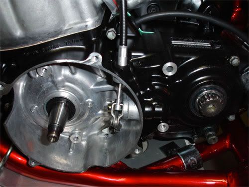
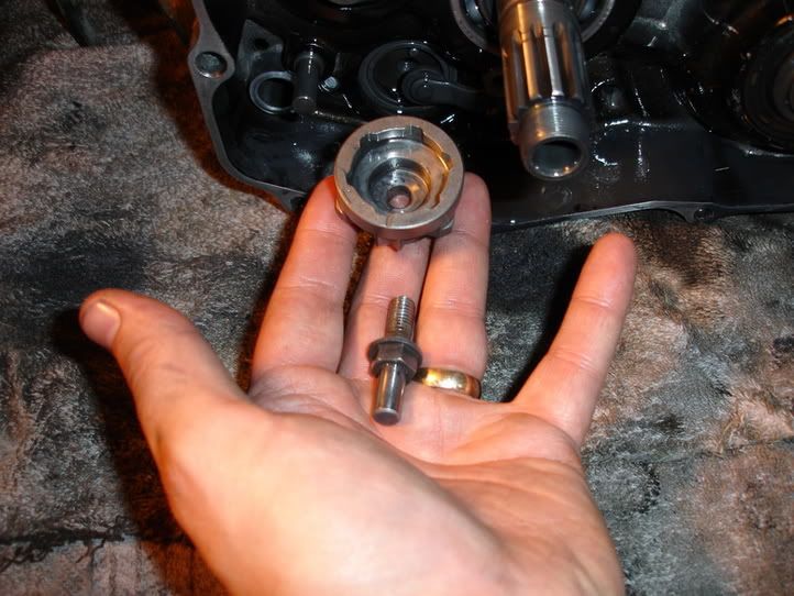
Flywheel/Stator Plate, WaterPump Gear and Counter Sprocket removal:
Remove Water Pump housing Cover and Metal Gasket:
Should Look Like this afterwards...
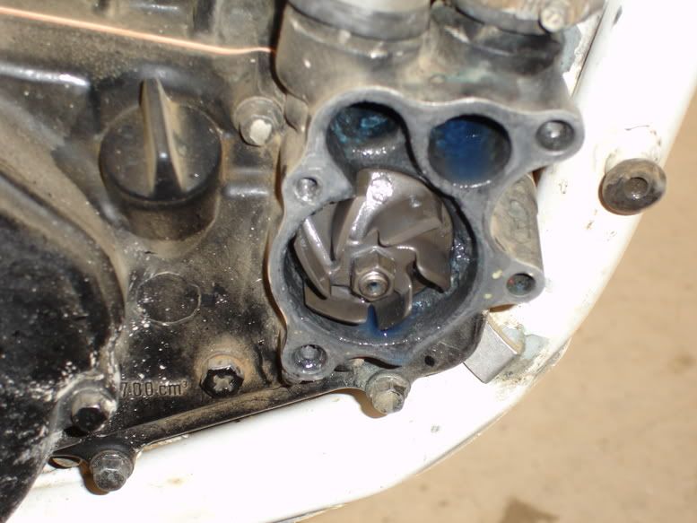
Pop Bike into first gear have a buddy or the old lady park their rump on the bike (frame) and apply both brakes....Brake torque and remove water pump impeller. Its number 1 in the exploded pic above. Bag up water-pump housing, hardware and impeller.
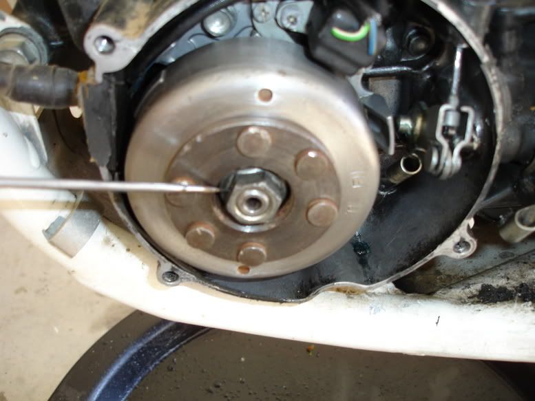
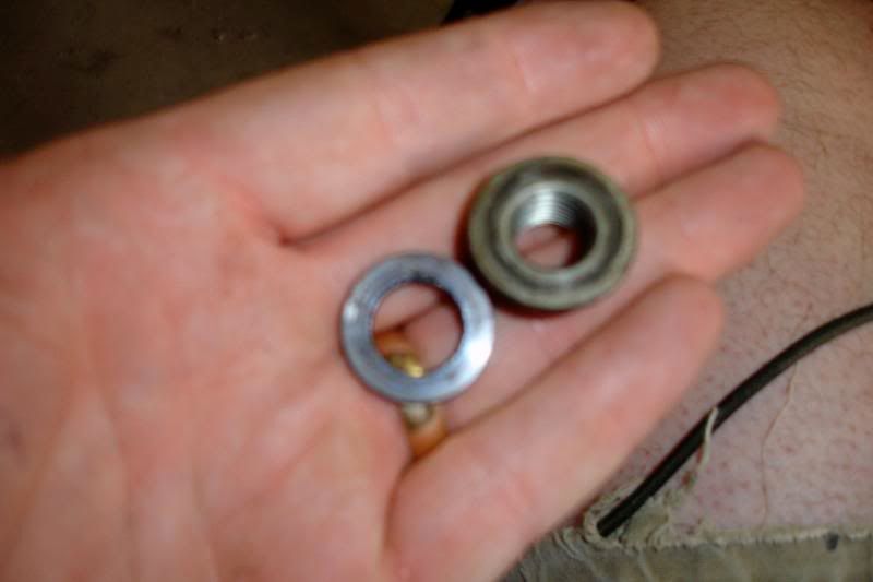
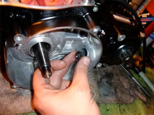
Remove Ignition Cover from left side of motor to expose flywheel. While a buddy still has the brakes applied...remove bolt and washer that secures Flywheel to Crank.....use a 1/2 Dr Breaker Bar.
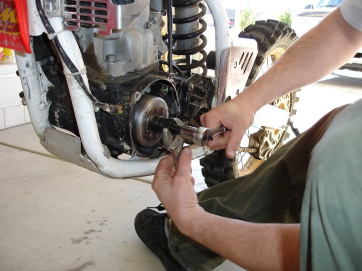
Pull out the handy Flywheel removal tool.
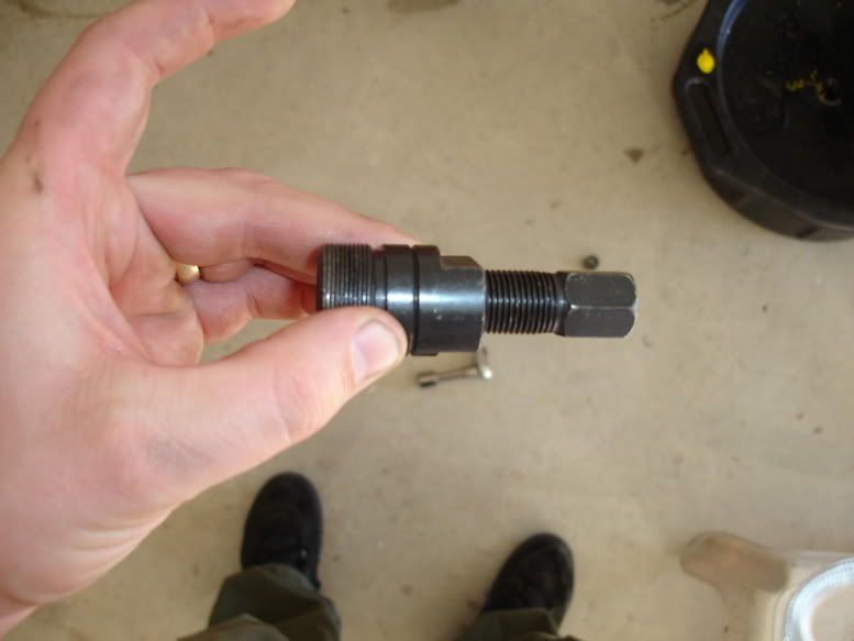
Apply grease to inner detail or bolt that contacts crank. This is so you do not mar the end of the crank. Thread outer detail into the Flywheel, till tight, then back it off quarter turn. Turn inner detail or bolt till it presses the flywheel off the crank. You will need two tools, one to turn the bolt and one to hold the portion that threads into Flywheel.
Next, you will see 2 ea bolts securing Stator Plate/Pulse Generator to Left Case...remove them and slide Stator Plate out and away from the motor. You will need to disconnect wires from CDI and pull wires/sealing grommet from case. Bag it all up..
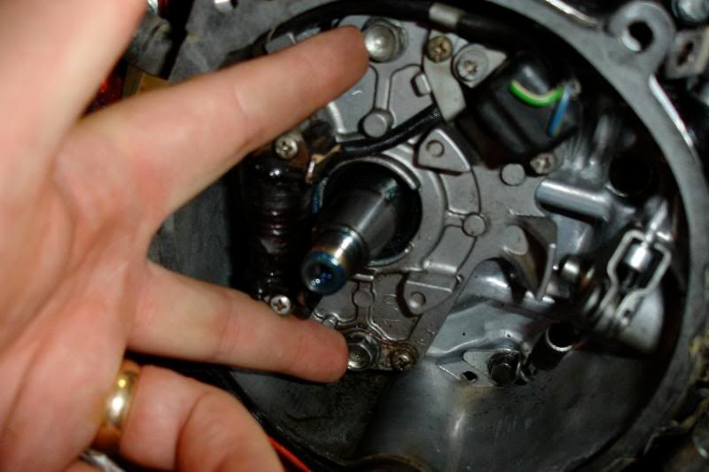
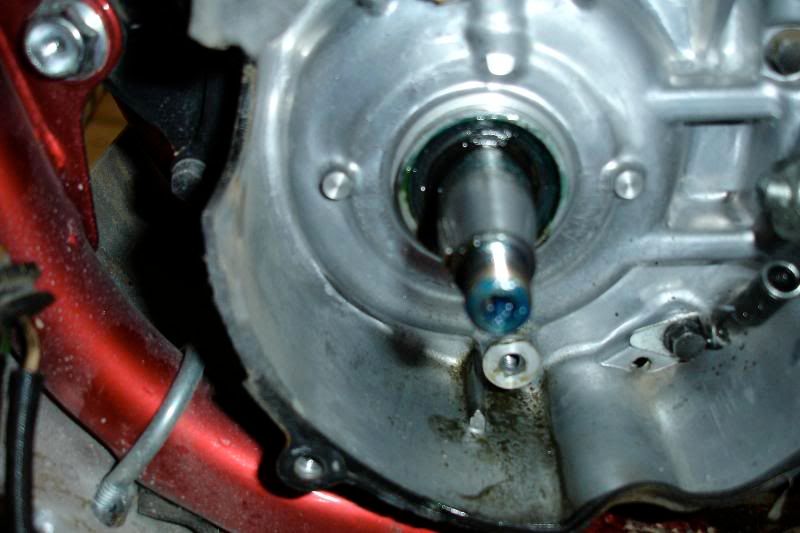
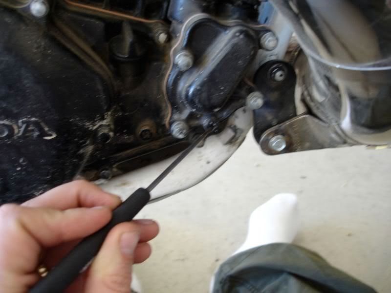
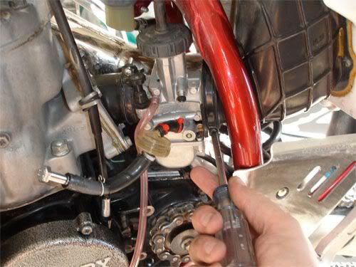
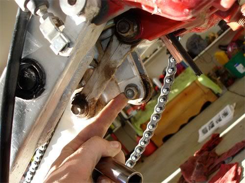
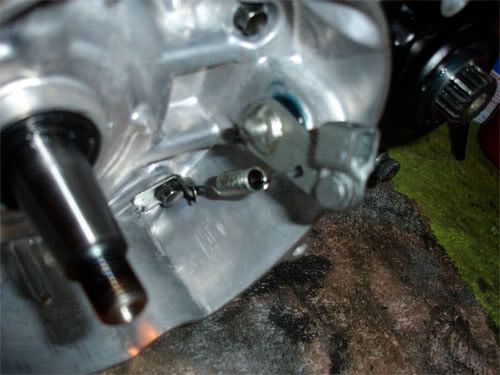
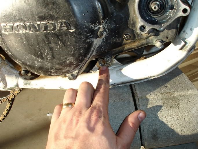
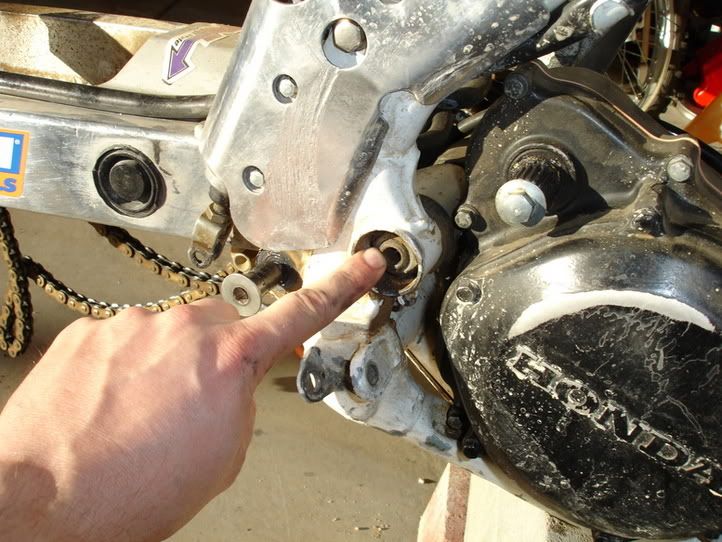
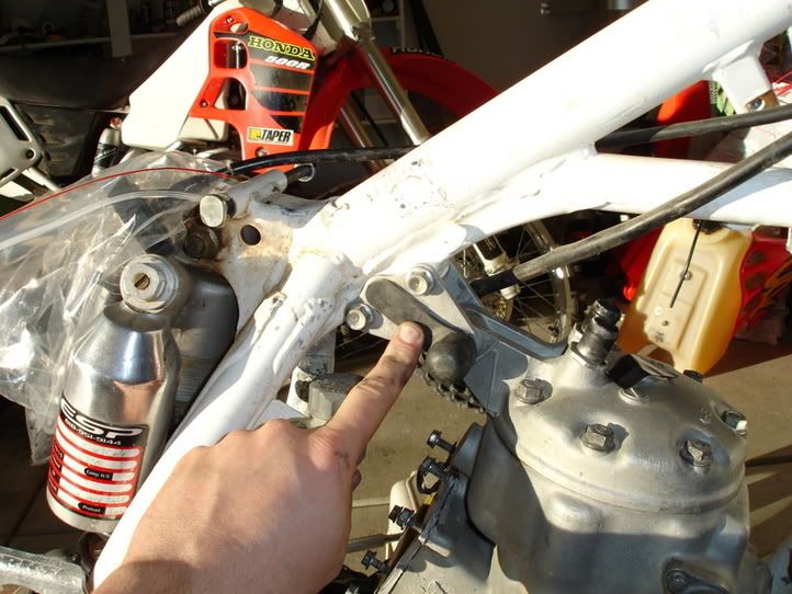
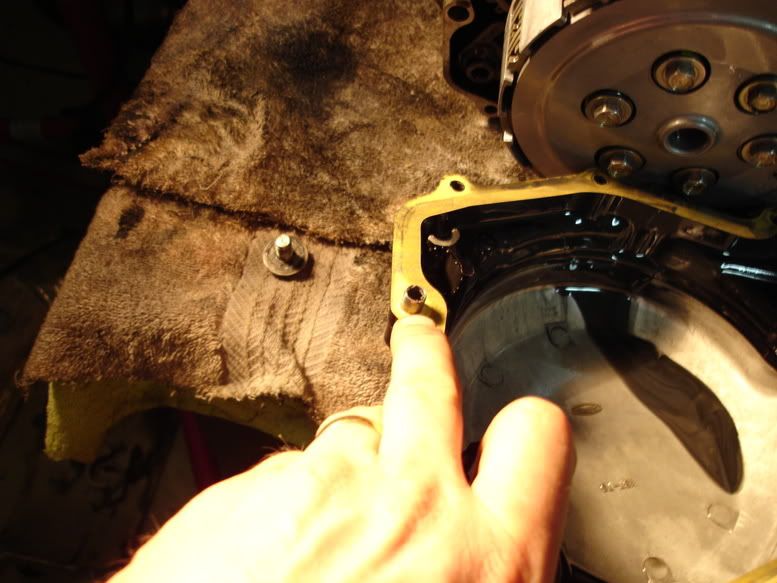
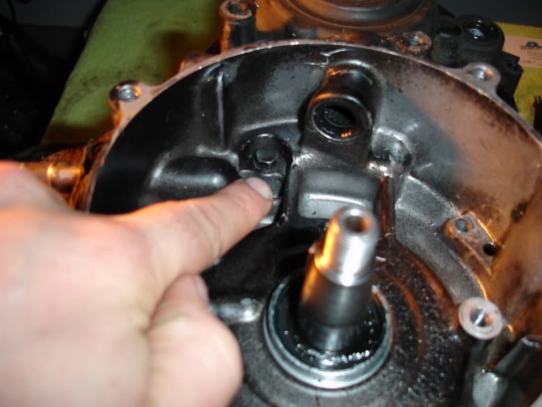
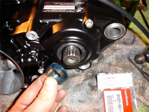
Remove Counter Sprocket Guard....finger bend clamp to release clutch cable.
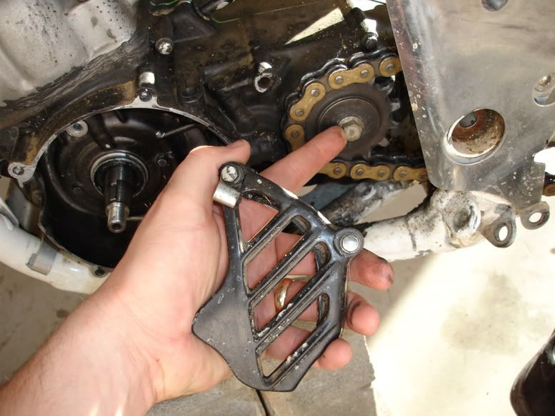
Break torque on bolt that secures Counter Sprocket. My booger-extractor is pointing at it in the above picture. Remove Bolt and Sprocket....drape chain.
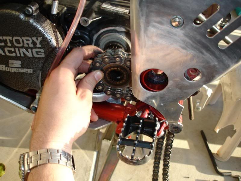
Your buddy and get off the bike and you can pop it back into neutral and put the bike on a stand for the remainder of the teardown.
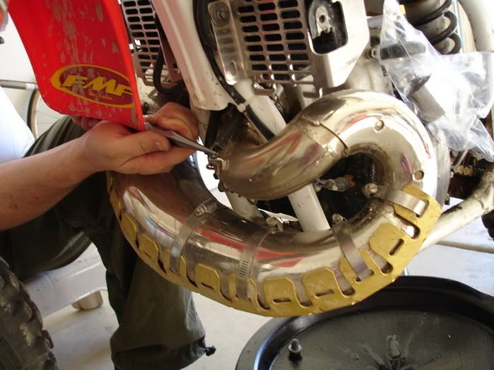
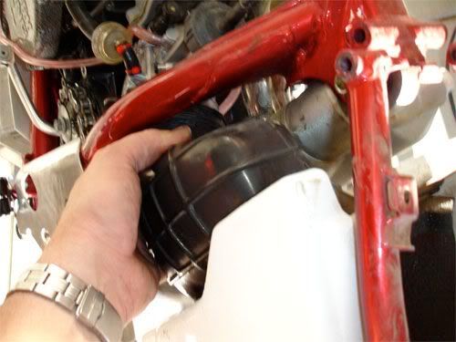
Pipe removal:
Remove Bolts securing Pipe to Frame....two locations. Then pull springs (4 each). Wiggle and remove pipe from Exhaust Port.
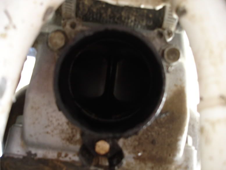
Exposed Exhaust Port. Now You can remove the Exhaust Port Adapter at this time as well. Makes pulling motor out a bit easier.
SubFrame Removal:
Loosen Carb aft clamp to Air Boot.
Remove two 2 ea lower mount bolts.
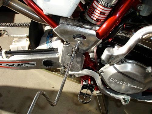
Remove Top Keyed Mount Bolt.
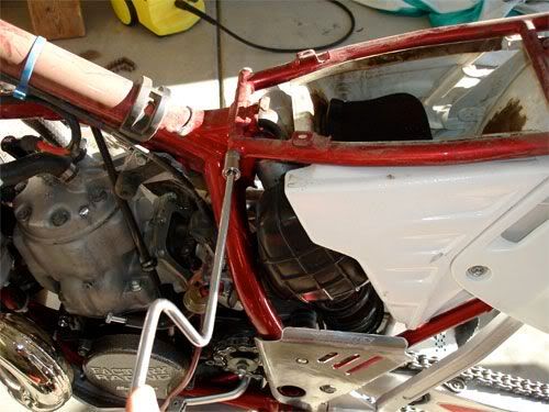
Break seal on at Air Boot and Carb, remove subframe.
Then put a bag over end of Carb....point is.....keep crap out of your carb unless you like surprises.
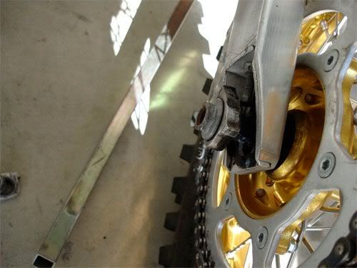
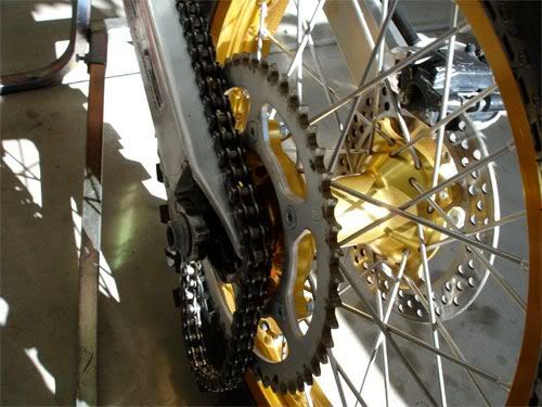
Rear Tire and Rear Shock Removal:
Break torque on NUT side of Rear Tire axle, use back up wrench. Remove nut.
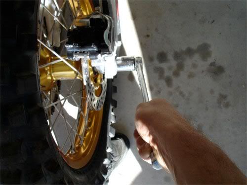
Slide axle somewhat out to release axle blocks:
Roll rear tire and remove chain from sprocket.
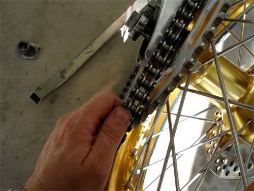
Pull rear axle out while supporting rear tire....a foot underneath it works well to free up your hands.
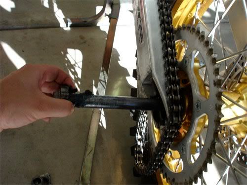
Now....lets pop those bolts off the Rear Shock. When applicable....ALWAYS break torque from nut side!!!!
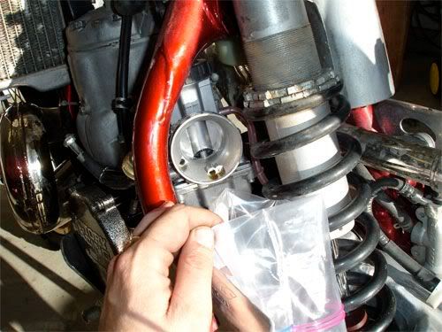
Carb removal:
Loosen up Cap, remove Slide and needle....snag a piece of styrofoam stick the needle in it to protect it....bag up slide, cap and needle.
Next, loosen up forward Carb Clamp.....remove Carb from Intake and pull all vent lines free of clamps.....drain Carb of excess fuel...bag whole carb!
Clutch Disco:
At the clutch lever, there should be a turnbuckle of sorts to adjust tension on your clutch cable. Got it? Good! Bust 2 jamnuts lose and loosen clutch cable by turning turnbuckle CLOCKWISE.
Now go down to Clutch Actuation Arm, you should be able remove Clutch Cable from Actuation Arm.
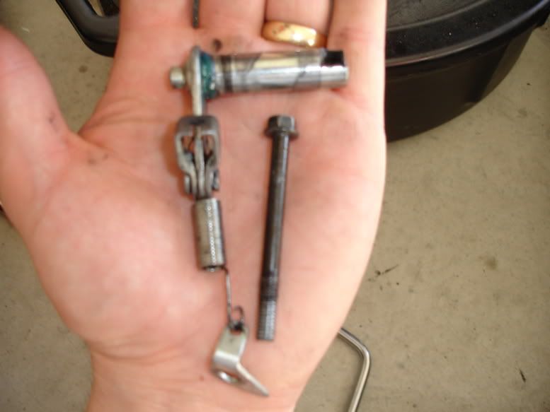
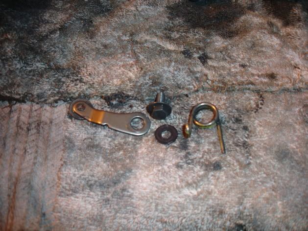
On 89 and older motors, there will be a spring attached to the Actuation Arm/Lever....loosen it and remove bolt securing Tab and Spring. *** If you bike does not have this...skip to next step***
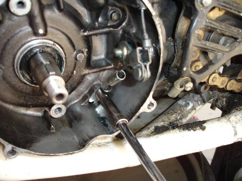
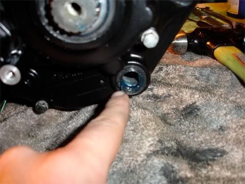
Remove Actuation Arm/Lever. Also pay notice....this lever rides on a seal. If you have a Tranny Leak in this area...change that seal.
Kickstarter removal:
Remove 1 ea bolt from Kickstart Lever and Kickstarter Spindle...wiggle Kickstarter off Spindle Splines.
Plug and Coolant/Rad Lines:
Take Plug Wrench and remove Spark Plug. Rip a piece of masking tape off and cover hole.
Disconnect 2 each hose clamps securing Coolant Lines to Head. Pop lines off and snug hose clamps back down on lines so they dont get lost. You will also need to disconnect Coolant Line from Water pump to Radiator.
Now the Good Book:
It tells me that 88 and newer bikes...the radiators must be removed.....
Rad Alt Method.... Remove 2 each aft bolts securing Rads to Frame. Next, remove 2 ea lower fwd mount bolts and LOOSEN upper fwd mount bolts.. Lastly, disconnect lower crossover coolant line between the rad's from one side...snug hose clamp back up once removed. Now you should have decent amount of play in the rad's.....push them forward and way from the motor. This should facilitate enough room to remove motor.
Bag up all your shit accordingly...per section/component.
Speedhandle setup, break torque and removed two each bolts that secure seat to SubFrame/Side Panels. and slide seat aft and up away from bike.
Gas Tank Removal:
Turn Petcock "off" and disconnect Carb Fuel Line. Cap off the Fuel Line to Carb...bolt works well. Remove 2ea bolts securing Shrouds to Radiators. Next, removed 2 ea inner bolts securing Tank to Frame. Unhook band from aft side of Tank and remove tank from bike.
Drain oil from Tranny:
Please use suitable container and dispose of responsibly.
Drain Engine Coolant:
First, remove radiator cap and set off to the side. Next have a container ready....remove drain bolt off Water Pump Housing. Catch any fluid that comes out...also lean the bike over a bit to help drain the system.
It is also a good idea to remove bolt in Cylinder and drain water jacket. Bolt right in the middle of the jug on the left side with copper crush washer. After Draining is completed, put drain bolts back in and put Radiator Cap back on.
Right Side Panel Removal:
Remove 1 each bolt. After panel is removed, you can put it back into subframe for easy build up.
Silencer Removal:
Remove 2 ea bolts securing Silencer to SubFrame. Wiggle silencer out of Expansion Chamber and pull out and away from bike. You can re-install silencer bolts back into SubFrame or bag them up.
Flywheel/Stator Plate, WaterPump Gear and Counter Sprocket removal:
Remove Water Pump housing Cover and Metal Gasket:
Should Look Like this afterwards...
Pop Bike into first gear have a buddy or the old lady park their rump on the bike (frame) and apply both brakes....Brake torque and remove water pump impeller. Its number 1 in the exploded pic above. Bag up water-pump housing, hardware and impeller.
Remove Ignition Cover from left side of motor to expose flywheel. While a buddy still has the brakes applied...remove bolt and washer that secures Flywheel to Crank.....use a 1/2 Dr Breaker Bar.
Pull out the handy Flywheel removal tool.
Apply grease to inner detail or bolt that contacts crank. This is so you do not mar the end of the crank. Thread outer detail into the Flywheel, till tight, then back it off quarter turn. Turn inner detail or bolt till it presses the flywheel off the crank. You will need two tools, one to turn the bolt and one to hold the portion that threads into Flywheel.
Next, you will see 2 ea bolts securing Stator Plate/Pulse Generator to Left Case...remove them and slide Stator Plate out and away from the motor. You will need to disconnect wires from CDI and pull wires/sealing grommet from case. Bag it all up..
Remove Counter Sprocket Guard....finger bend clamp to release clutch cable.
Break torque on bolt that secures Counter Sprocket. My booger-extractor is pointing at it in the above picture. Remove Bolt and Sprocket....drape chain.
Your buddy and get off the bike and you can pop it back into neutral and put the bike on a stand for the remainder of the teardown.
Pipe removal:
Remove Bolts securing Pipe to Frame....two locations. Then pull springs (4 each). Wiggle and remove pipe from Exhaust Port.
Exposed Exhaust Port. Now You can remove the Exhaust Port Adapter at this time as well. Makes pulling motor out a bit easier.
SubFrame Removal:
Loosen Carb aft clamp to Air Boot.
Remove two 2 ea lower mount bolts.
Remove Top Keyed Mount Bolt.
Break seal on at Air Boot and Carb, remove subframe.
Then put a bag over end of Carb....point is.....keep crap out of your carb unless you like surprises.
Rear Tire and Rear Shock Removal:
Break torque on NUT side of Rear Tire axle, use back up wrench. Remove nut.
Slide axle somewhat out to release axle blocks:
Roll rear tire and remove chain from sprocket.
Pull rear axle out while supporting rear tire....a foot underneath it works well to free up your hands.
Now....lets pop those bolts off the Rear Shock. When applicable....ALWAYS break torque from nut side!!!!
Carb removal:
Loosen up Cap, remove Slide and needle....snag a piece of styrofoam stick the needle in it to protect it....bag up slide, cap and needle.
Next, loosen up forward Carb Clamp.....remove Carb from Intake and pull all vent lines free of clamps.....drain Carb of excess fuel...bag whole carb!
Clutch Disco:
At the clutch lever, there should be a turnbuckle of sorts to adjust tension on your clutch cable. Got it? Good! Bust 2 jamnuts lose and loosen clutch cable by turning turnbuckle CLOCKWISE.
Now go down to Clutch Actuation Arm, you should be able remove Clutch Cable from Actuation Arm.
On 89 and older motors, there will be a spring attached to the Actuation Arm/Lever....loosen it and remove bolt securing Tab and Spring. *** If you bike does not have this...skip to next step***
Remove Actuation Arm/Lever. Also pay notice....this lever rides on a seal. If you have a Tranny Leak in this area...change that seal.
Kickstarter removal:
Remove 1 ea bolt from Kickstart Lever and Kickstarter Spindle...wiggle Kickstarter off Spindle Splines.
Plug and Coolant/Rad Lines:
Take Plug Wrench and remove Spark Plug. Rip a piece of masking tape off and cover hole.
Disconnect 2 each hose clamps securing Coolant Lines to Head. Pop lines off and snug hose clamps back down on lines so they dont get lost. You will also need to disconnect Coolant Line from Water pump to Radiator.
Now the Good Book:
It tells me that 88 and newer bikes...the radiators must be removed.....
Rad Alt Method.... Remove 2 each aft bolts securing Rads to Frame. Next, remove 2 ea lower fwd mount bolts and LOOSEN upper fwd mount bolts.. Lastly, disconnect lower crossover coolant line between the rad's from one side...snug hose clamp back up once removed. Now you should have decent amount of play in the rad's.....push them forward and way from the motor. This should facilitate enough room to remove motor.
Bag up all your shit accordingly...per section/component.
Last edited by Rosco-Peeko on April 1st, 2010, 9:21 pm, edited 4 times in total.
Somewhere in Kenya, a village is missing their idiot.......
-
Rosco-Peeko
- Posts: 823
- Joined: June 1st, 2007, 2:47 pm
Part III Engine Removal
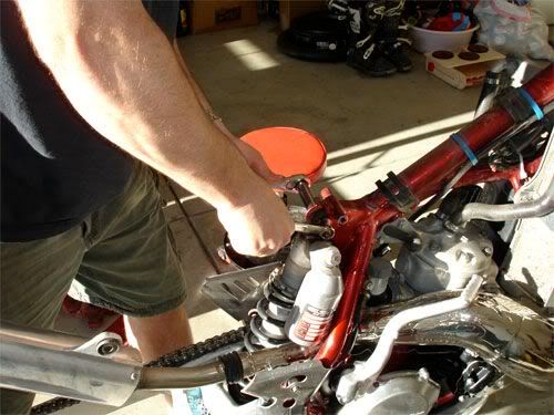
Breaking Torque:
With the motor still in the frame and tight.....use that to your advantage! Break the Cylinder and Head Nuts loose. Do not remove them....just bust torque.
Motor Mounts:
Break em loose....
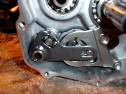
Head-Stay:
Motor removal:
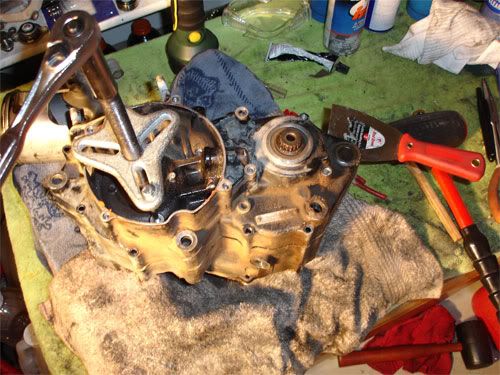
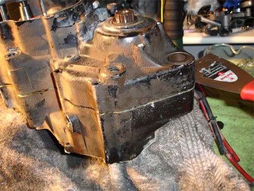
Remove Head-Stay, Aft Pivot Mount, Lower Mount and Front Mount. You will have to wiggle motor to get mounts all the way out. Once the all the mounts are removed. Pull Swingarm aft and clear of the motor. Now at times you may have to slide CDI out of the way to facilitate motor removal. Carefully slide motor out of frame from the left side.
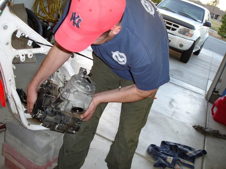
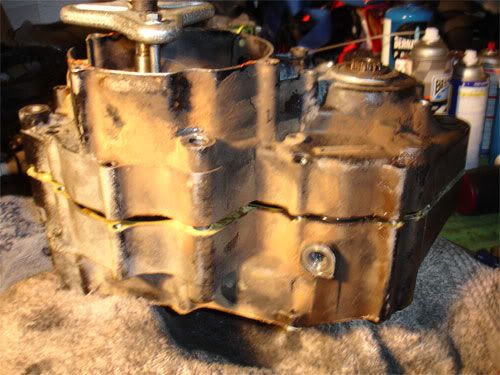
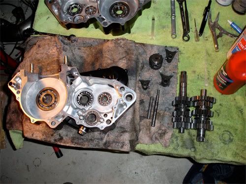
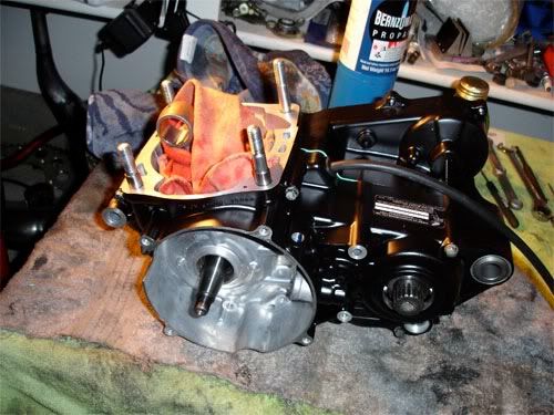
Set Motor on workbench. Note, I left the Reed Block installed for a reason...keep crap out of the motor.
Bag up everything per section.
You will note that I tore my bike down further that what is indicated... My bike was getting "The Treatment"....
With the motor still in the frame and tight.....use that to your advantage! Break the Cylinder and Head Nuts loose. Do not remove them....just bust torque.
Motor Mounts:
Break em loose....
Head-Stay:
Motor removal:
Remove Head-Stay, Aft Pivot Mount, Lower Mount and Front Mount. You will have to wiggle motor to get mounts all the way out. Once the all the mounts are removed. Pull Swingarm aft and clear of the motor. Now at times you may have to slide CDI out of the way to facilitate motor removal. Carefully slide motor out of frame from the left side.
Set Motor on workbench. Note, I left the Reed Block installed for a reason...keep crap out of the motor.
Bag up everything per section.
You will note that I tore my bike down further that what is indicated... My bike was getting "The Treatment"....
Somewhere in Kenya, a village is missing their idiot.......
-
Rosco-Peeko
- Posts: 823
- Joined: June 1st, 2007, 2:47 pm
Part IV Right Cover/Clutch/Shift Assy Removal
Right Cover Removal:
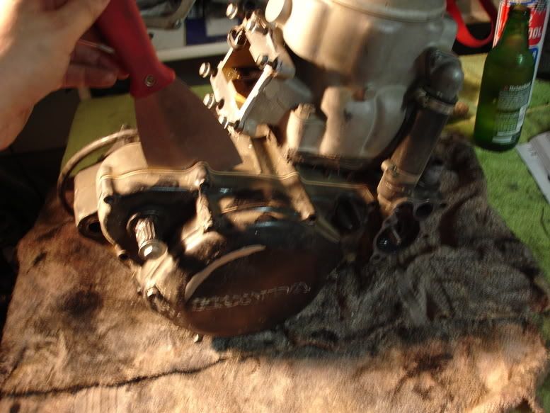
First....remove Coolant Line from Cylinder/Waterpump....bag it up. Next, remove all bolts securing Right Cover to Right Case. Now....break out the spackle knife and mallet. A few light taps to break the seal on the gasket or to create a gap. Slide the spackle knife in and work it around..CAREFULLY! You do not want to hose up your mating surfaces......a screwstik (screwdriver) is an absolute no-no! Work right cover off evenly.
Remove Water Pump Gear:
Make sure all of your Dowel Locating Pins are accounted for...there are 2ea, 180 degree's out from each other. Bag them up if they are loose.
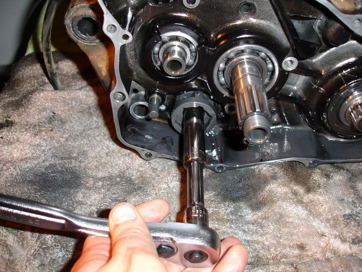
Primary Drive Gear:
Lets Break torque on this bad boy while we can. Wedge a penny between the Primary Drive Gear and Clutch. With a breaker bar break toque on it.....be sure to get a good full turn on it. The penny will be mangled...but served its purpose and soft enough not to damage anything.
Clutch Removal:
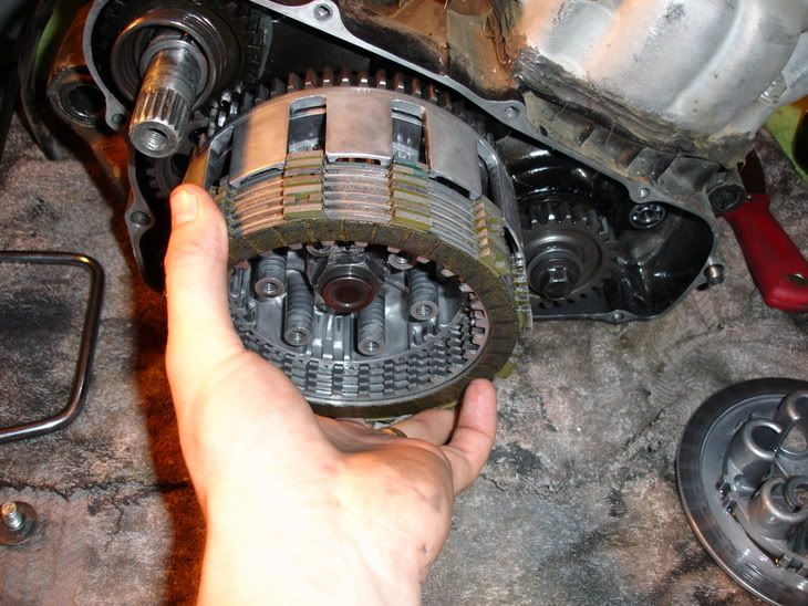
Remove 6 each bolts and springs on Pressure Plate.
Remove all Clutch Plates and bag em up...they will need to be inspected later. Unless you plan on changing them.
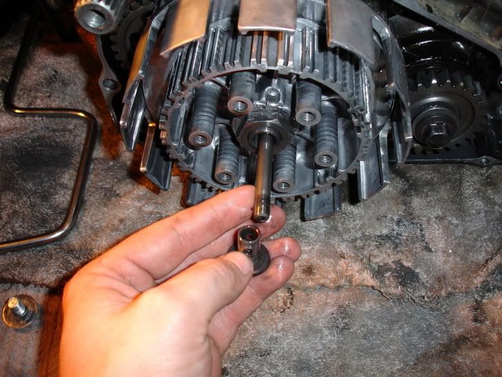
Remove Clutch Lifter and Pushrod and in my case (90 and older) there is a BB between the Lifter and Pushrod....DONT loose it.
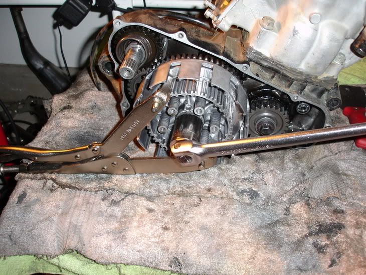
Bend Locking Tab's Washer off locknut....break out "The Grabbit" (Chingus) and lock it onto the Clutch Center in a fashion that you can work a breaker bar and the Grabbit wedges down on the table.....effectively freeing up a hand to hold motor.
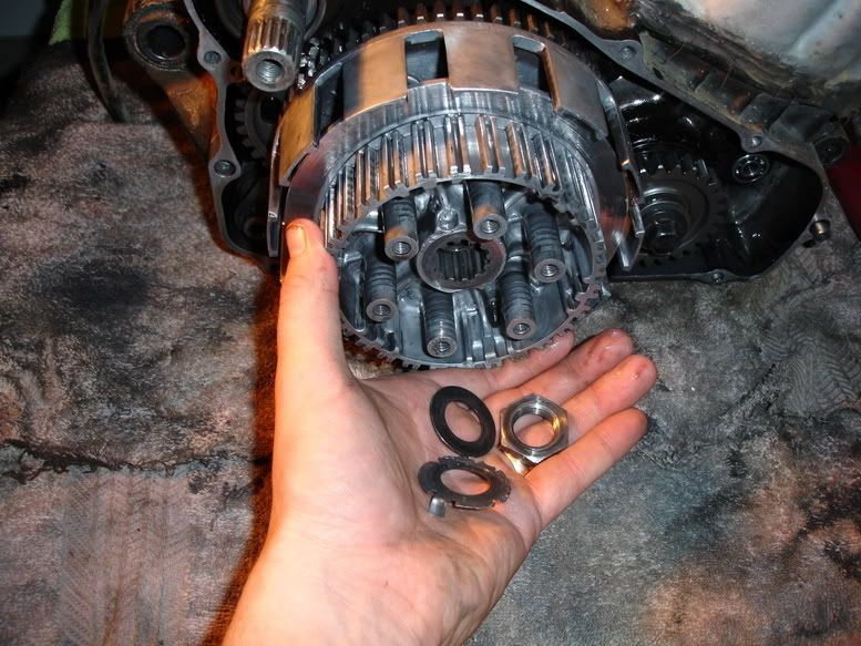
Remove Clutch Center, Locking Washer....(buy a new one...shitcan old one) Nut and washer.
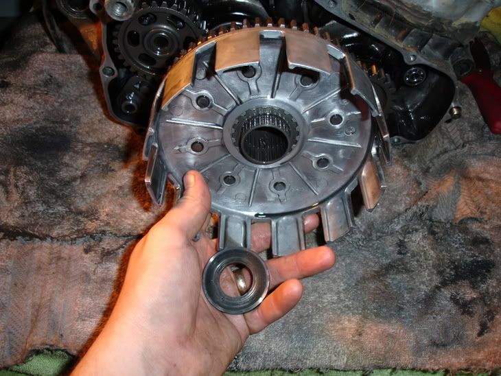
Remove thick washer and Clutch Basket....remember the order!
Slide off Sleeve and Needle Bearings off MainShaft....
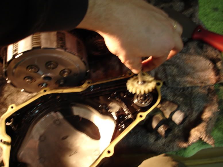
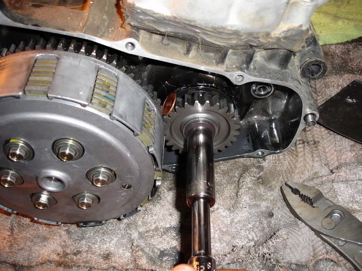
Now Remove that Primary Drive Gear.
Slide Idler Gear off Countershaft.....dont forget the flanged bushing it rides on...flanged side toward the bearing/case.
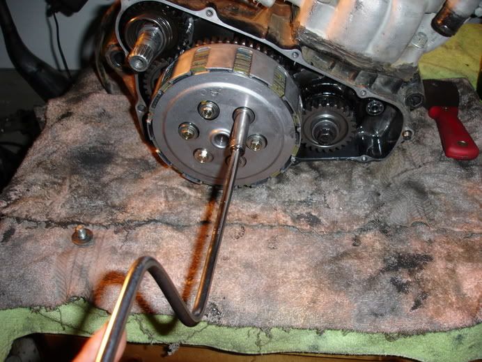
Pull Spring end out of case, apply slight inward pressure and clock Kickstart Spindle counter-clockwise until its pops free.
Keep it all together in one bag and dont upset the peened marks. This is important during re-assembly....We'll cover it again.
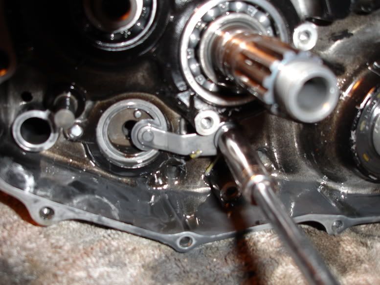
Shift Linkage Disco:
***Note*** Bagging of parts after disassembly is critical...too many small parts to loose!!!!! So if you've been drinking too much beer and have as much agility/dexterity as Edward Penis-Fingers....save it for the next day.
Disconnect Shift Lever on left side of the motor, then pull Gearshift Spindle and Washer free of motor...bag it....
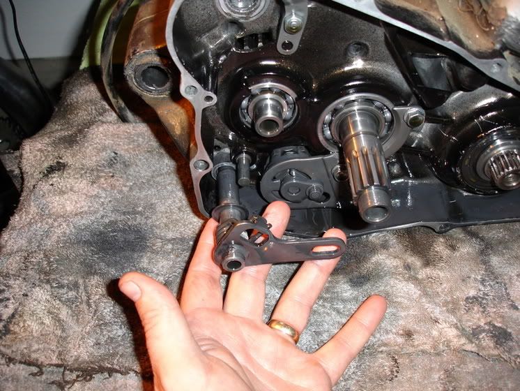
Please be aware of the shifter collar...dont loose it! Tiny little bushing.
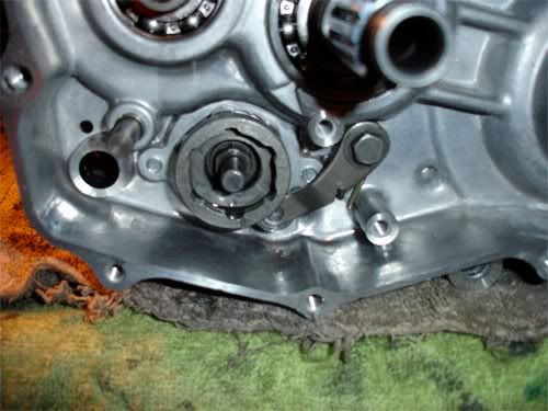
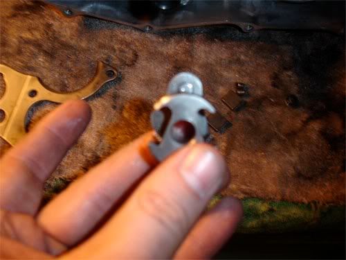
Remove Guide Plate via 3 bolts. During this step you will CAREFULLY remove Drum Shifter with Guide Plate. It has subparts that are easy to lose. Shifter Collar includes; Springs 2ea, Plungers 2 ea and Ratchet Pawls 2 ea...all of which are in second pic.
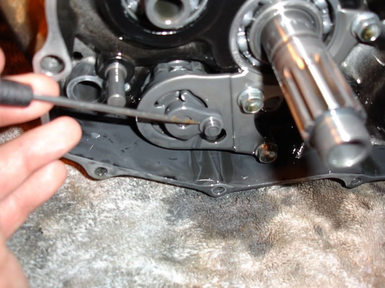
Remove center pin from Drum Center. Remove Drum Center.
Remove Stopper Arm. Note that it is under spring pressure and has 1 bolt and washer.
General Insp:
1) Inspect your Clutch Lifter Pushrod for straightness and or any damage. Roll it on a flat surface to ensure it not bent.
2) Check Lifter and Lifter needle bearing (as applicable) for damage and freedom of movement.
3) Clutch Lifter/Actuation Arm, look for damage and obvious wear.
4) Clutch Spring Inspection, you will need a Vanier Caliper. Spring Height should be as follows:
85-89 1.67 inches or 42.5MM
After 89 1.66 inches or 42.2MM
5) Clutch Disk, measure thickness with a vanier caliper for a minimum of 0.112 inch/2.85MM thickness.....replace if its less. Beware...this is for Honda Disks, aftermarket disks thickness may vary or be "slightly" different. Use your best judgement.
6) Clutch Plates, Check for warpage.....on flat surface, attempt to slide a 0.008 inch/0.2MM feeler gauge under disk with equal finger pressure applied on disk.
7) Clutch Basket, look for grooved fingers from clutch plates...there in no service limit....use your best judgement.
A) Measure ID (Inner Diameter) of Clutch basket with vanier caliper, service limit is 1.2620/32.054MM...if you exceed this....replace basket. This measurement is taken where the basket rides on the Clutch Outer Guide/Needle Bearings.
8. Clutch Outer Guide, this is what your Clutch Basket rides on. Looks like a simple flanged bushing. After 85 this applies, measure its OD (outer
diameter) service limit is 1.1013 inches/27.973MM, replace if its less than this...
9) Clutch Basket Needle Bearings...use your best judgement....are the needles frosted, pitted, galled, busted pins and freedom of rotation?
10) Kickstart Return Spring, check for weakness or general damage.
11) Kickstart Spindle OD, measure it with vaneir caliper or outside mic. Service limit is 0.864 inches/21.95MM..if its less...replaces. This measurement is taken where the Pinion Gear rides.
12) Kickstarter Pinion Gear, measure the ID (Inner Diameter) of where it rides on Kickstarter Spindle. Service Limit is 0.790 inches/20.06MM.
13) Idler Gear, measure its ID, Service Limit is 0.790 inches/20.07MM
14) Counter Shaft OD, where Idler Gear rides. Service Limit is 0.0667 inches/16.95MM
15) Idler Gear Bushing ID, Service Limit is 0.0671 inches/17.04MM
16) Idler Gear Bushing OD, Service Limit is 0.786 inches/19.96MM
17) Water Pump Gear:
A) Look for cracks, fractures, worn teeth...etc
B) Observe Water Pump Gear Shaft for grooves from seals...if a fingernail can catch these grooves...REPLACE your Water Pump Gear Shaft.
18. Plan on replacing both Water Pump Seals.......
19) Water Pump Bearing, inspect for excessive wear, noisy movement...should spin freely and quietly. You insert the Pump Shaft into bearing...excessive up and down movement....replace it.
20) Water Pump Impeller, general damage, hosed up threads...etc. Ensure you retain the copper thrust washer...
End of section...ensure you have everything and all is bagged up per section.
First....remove Coolant Line from Cylinder/Waterpump....bag it up. Next, remove all bolts securing Right Cover to Right Case. Now....break out the spackle knife and mallet. A few light taps to break the seal on the gasket or to create a gap. Slide the spackle knife in and work it around..CAREFULLY! You do not want to hose up your mating surfaces......a screwstik (screwdriver) is an absolute no-no! Work right cover off evenly.
Remove Water Pump Gear:
Make sure all of your Dowel Locating Pins are accounted for...there are 2ea, 180 degree's out from each other. Bag them up if they are loose.
Primary Drive Gear:
Lets Break torque on this bad boy while we can. Wedge a penny between the Primary Drive Gear and Clutch. With a breaker bar break toque on it.....be sure to get a good full turn on it. The penny will be mangled...but served its purpose and soft enough not to damage anything.
Clutch Removal:
Remove 6 each bolts and springs on Pressure Plate.
Remove all Clutch Plates and bag em up...they will need to be inspected later. Unless you plan on changing them.
Remove Clutch Lifter and Pushrod and in my case (90 and older) there is a BB between the Lifter and Pushrod....DONT loose it.
Bend Locking Tab's Washer off locknut....break out "The Grabbit" (Chingus) and lock it onto the Clutch Center in a fashion that you can work a breaker bar and the Grabbit wedges down on the table.....effectively freeing up a hand to hold motor.
Remove Clutch Center, Locking Washer....(buy a new one...shitcan old one) Nut and washer.
Remove thick washer and Clutch Basket....remember the order!
Slide off Sleeve and Needle Bearings off MainShaft....
Now Remove that Primary Drive Gear.
Slide Idler Gear off Countershaft.....dont forget the flanged bushing it rides on...flanged side toward the bearing/case.
Pull Spring end out of case, apply slight inward pressure and clock Kickstart Spindle counter-clockwise until its pops free.
Keep it all together in one bag and dont upset the peened marks. This is important during re-assembly....We'll cover it again.
Shift Linkage Disco:
***Note*** Bagging of parts after disassembly is critical...too many small parts to loose!!!!! So if you've been drinking too much beer and have as much agility/dexterity as Edward Penis-Fingers....save it for the next day.
Disconnect Shift Lever on left side of the motor, then pull Gearshift Spindle and Washer free of motor...bag it....
Please be aware of the shifter collar...dont loose it! Tiny little bushing.
Remove Guide Plate via 3 bolts. During this step you will CAREFULLY remove Drum Shifter with Guide Plate. It has subparts that are easy to lose. Shifter Collar includes; Springs 2ea, Plungers 2 ea and Ratchet Pawls 2 ea...all of which are in second pic.
Remove center pin from Drum Center. Remove Drum Center.
Remove Stopper Arm. Note that it is under spring pressure and has 1 bolt and washer.
General Insp:
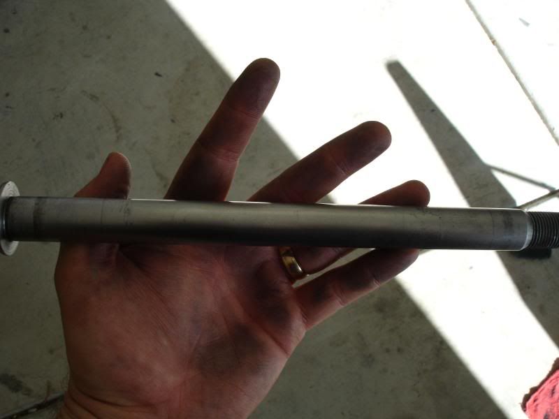
1) Inspect your Clutch Lifter Pushrod for straightness and or any damage. Roll it on a flat surface to ensure it not bent.
2) Check Lifter and Lifter needle bearing (as applicable) for damage and freedom of movement.
3) Clutch Lifter/Actuation Arm, look for damage and obvious wear.
4) Clutch Spring Inspection, you will need a Vanier Caliper. Spring Height should be as follows:
85-89 1.67 inches or 42.5MM
After 89 1.66 inches or 42.2MM
5) Clutch Disk, measure thickness with a vanier caliper for a minimum of 0.112 inch/2.85MM thickness.....replace if its less. Beware...this is for Honda Disks, aftermarket disks thickness may vary or be "slightly" different. Use your best judgement.
6) Clutch Plates, Check for warpage.....on flat surface, attempt to slide a 0.008 inch/0.2MM feeler gauge under disk with equal finger pressure applied on disk.
7) Clutch Basket, look for grooved fingers from clutch plates...there in no service limit....use your best judgement.
A) Measure ID (Inner Diameter) of Clutch basket with vanier caliper, service limit is 1.2620/32.054MM...if you exceed this....replace basket. This measurement is taken where the basket rides on the Clutch Outer Guide/Needle Bearings.
8. Clutch Outer Guide, this is what your Clutch Basket rides on. Looks like a simple flanged bushing. After 85 this applies, measure its OD (outer
diameter) service limit is 1.1013 inches/27.973MM, replace if its less than this...
9) Clutch Basket Needle Bearings...use your best judgement....are the needles frosted, pitted, galled, busted pins and freedom of rotation?
10) Kickstart Return Spring, check for weakness or general damage.
11) Kickstart Spindle OD, measure it with vaneir caliper or outside mic. Service limit is 0.864 inches/21.95MM..if its less...replaces. This measurement is taken where the Pinion Gear rides.
12) Kickstarter Pinion Gear, measure the ID (Inner Diameter) of where it rides on Kickstarter Spindle. Service Limit is 0.790 inches/20.06MM.
13) Idler Gear, measure its ID, Service Limit is 0.790 inches/20.07MM
14) Counter Shaft OD, where Idler Gear rides. Service Limit is 0.0667 inches/16.95MM
15) Idler Gear Bushing ID, Service Limit is 0.0671 inches/17.04MM
16) Idler Gear Bushing OD, Service Limit is 0.786 inches/19.96MM
17) Water Pump Gear:
A) Look for cracks, fractures, worn teeth...etc
B) Observe Water Pump Gear Shaft for grooves from seals...if a fingernail can catch these grooves...REPLACE your Water Pump Gear Shaft.
18. Plan on replacing both Water Pump Seals.......
19) Water Pump Bearing, inspect for excessive wear, noisy movement...should spin freely and quietly. You insert the Pump Shaft into bearing...excessive up and down movement....replace it.
20) Water Pump Impeller, general damage, hosed up threads...etc. Ensure you retain the copper thrust washer...
End of section...ensure you have everything and all is bagged up per section.
Last edited by Rosco-Peeko on April 15th, 2010, 5:24 pm, edited 4 times in total.
Somewhere in Kenya, a village is missing their idiot.......
-
Rosco-Peeko
- Posts: 823
- Joined: June 1st, 2007, 2:47 pm
Part V Top End Removal
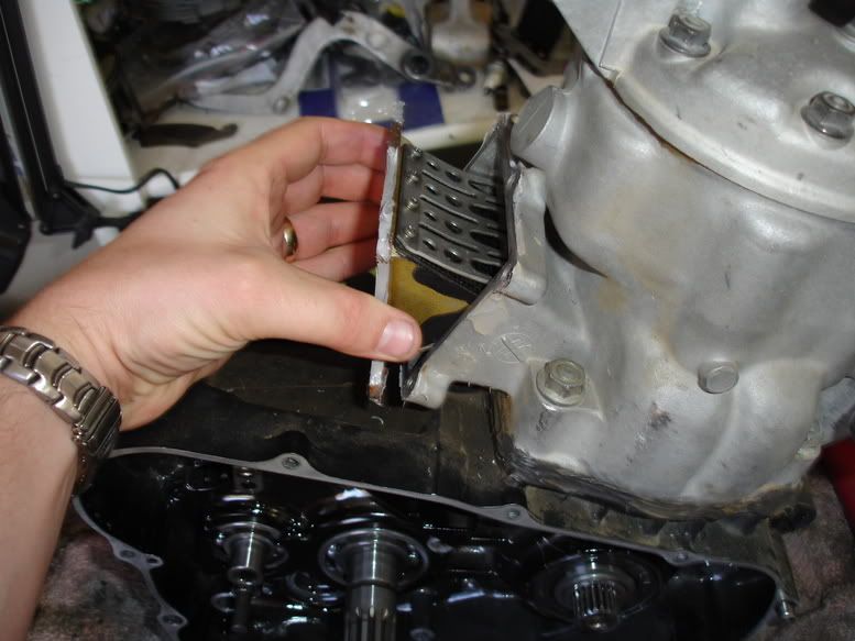
Reed Block:
Remove 6ea bolts, give assy a slight tap on each side with soft face mallet to break seal. Remove Reed Block.
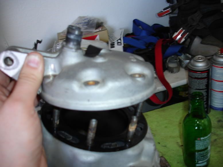
Head:
Remove 7ea nuts and remove Head and Metal Gasket. If you're in a pinch....you can re-use the Head Gasket....look for obvious damage and spray down with Copper-Kote Sealant. If not....trash it.
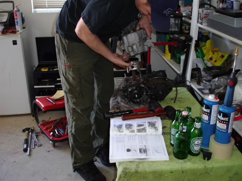
Cylinder:
Remove 4ea Cylinder Nuts. Get the Dead Blow Mallet.... a few good whacks in a 45 degree upward angle should unseat it. Be advised, there are 2 ea dowels that will make this a slow process...be PATIENT! Once unseated....DO NOT twist Cylinder unless you want to snag a ring and FOD out your bottom end. Two thumbs on Piston Crown and remaining fingers under Cylinder...pull straight up and push Piston down with thumbs.
Now wrap a shop rag around the Connecting Rod to protect it and to keep crap from falling in the bottom end. Pick a side of the Piston, use a scribe and pop a Circlip out. Press Wrist-Pin out from opposite side and remove Piston and Needle Bearing.
Bag up all of your stuff. Inspect Seating surfaces of Head, Cylinder and Cases...ensure no gouges! Bag head up, Add oil to Cylinder wall to keep corrosion down and route to a good machinist.
Machinist To-Do's:
Machinist inspect your Head's Mating Surface with a Straightedge to determine if its warped. Service Limit is 0.002 inch
Have them inspect the top of the Cylinder (Head mating surface), with a Straightedge to determine if its warped. Service Limit is 0.002 inch.
Have them Measure Inner Diameter of Cylinder for any Out of Round Conditions and set you up with a new Top End (0.003 Piston to Cylinder Clearance is Prime) and have them Bore/Hone accordingly....please ensure they use a Torque Plate!!!! See Bob's Cylinder Talk Thread for more info.
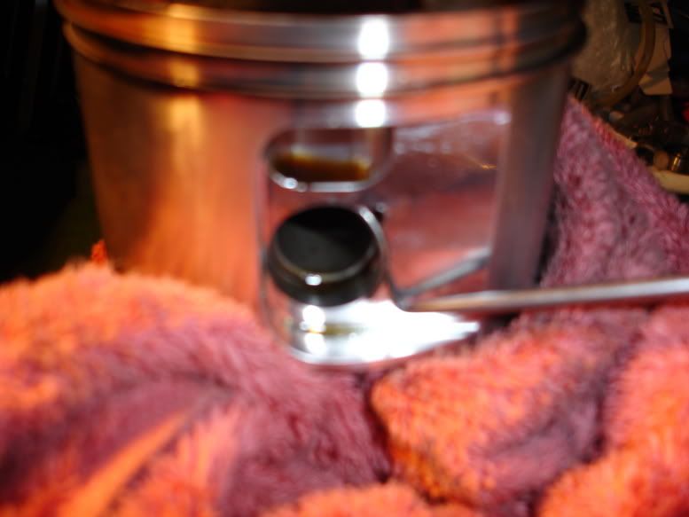
After All Honing/Bore is completed....ensure the machinist chamfered your ports and relieved the Exhaust Port Bridge.
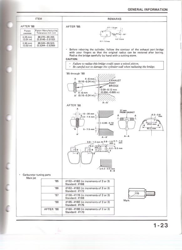
If you are running a new Wiseco Piston. You will need to drill the Exhaust Skirt. Not required on a cast piston.
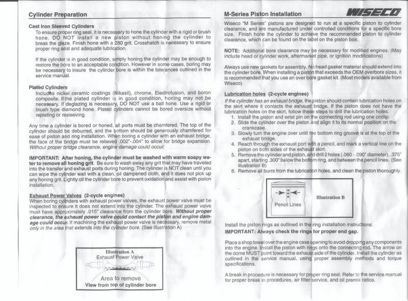
Reed Block Inspection:
Two most common Reeds on the CR500.....sorry didn't have a Rad Valve.
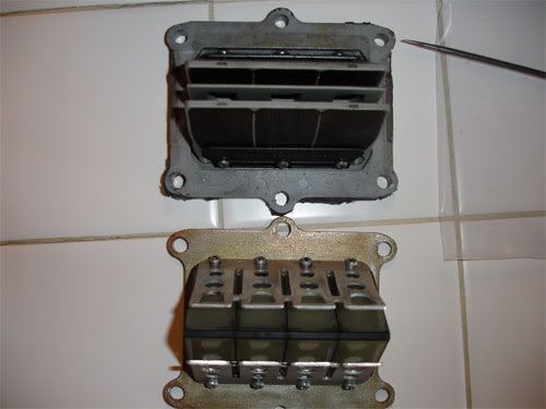
Inspect Pedals for chipped corners, cracks, missing pieces...
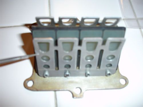
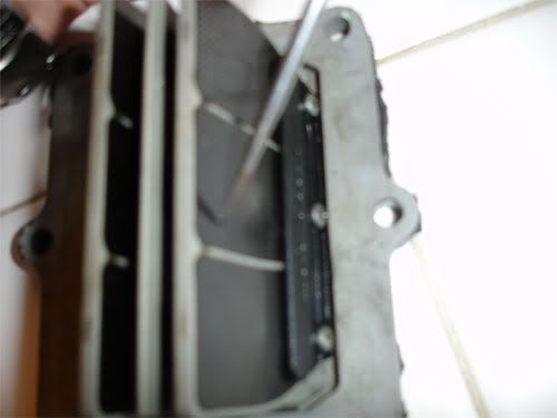
Inspect Stops for any damage...quite rare...or missing screws. Chances are...if there is a screw missing......where did it go? Cold uncomfortable sweat....
Look at Pedals from inside the Valve...you should see NO daylight between the Pedals and Valve, if you do....replace pedals.
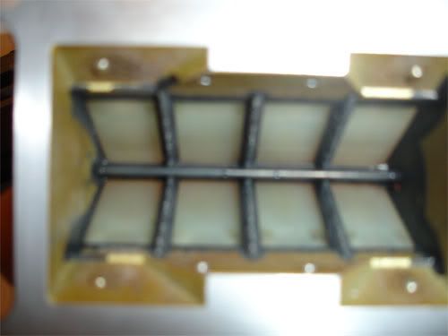
Next take a Straightedge and inspect for warpage on the back portion of Valve where it mates up to the Carb Insulator Boot. Service Limit is 0.004 checked wit a feeler gauge on the STOCK Valve. Replace as needed.
Carb Insulator Boot:
Check the rubber potion for cuts/tears or any deficiency that would introduce an air leak into system.
Remove 6ea bolts, give assy a slight tap on each side with soft face mallet to break seal. Remove Reed Block.
Head:
Remove 7ea nuts and remove Head and Metal Gasket. If you're in a pinch....you can re-use the Head Gasket....look for obvious damage and spray down with Copper-Kote Sealant. If not....trash it.
Cylinder:
Remove 4ea Cylinder Nuts. Get the Dead Blow Mallet.... a few good whacks in a 45 degree upward angle should unseat it. Be advised, there are 2 ea dowels that will make this a slow process...be PATIENT! Once unseated....DO NOT twist Cylinder unless you want to snag a ring and FOD out your bottom end. Two thumbs on Piston Crown and remaining fingers under Cylinder...pull straight up and push Piston down with thumbs.
Now wrap a shop rag around the Connecting Rod to protect it and to keep crap from falling in the bottom end. Pick a side of the Piston, use a scribe and pop a Circlip out. Press Wrist-Pin out from opposite side and remove Piston and Needle Bearing.
Bag up all of your stuff. Inspect Seating surfaces of Head, Cylinder and Cases...ensure no gouges! Bag head up, Add oil to Cylinder wall to keep corrosion down and route to a good machinist.
Machinist To-Do's:
Machinist inspect your Head's Mating Surface with a Straightedge to determine if its warped. Service Limit is 0.002 inch
Have them inspect the top of the Cylinder (Head mating surface), with a Straightedge to determine if its warped. Service Limit is 0.002 inch.
Have them Measure Inner Diameter of Cylinder for any Out of Round Conditions and set you up with a new Top End (0.003 Piston to Cylinder Clearance is Prime) and have them Bore/Hone accordingly....please ensure they use a Torque Plate!!!! See Bob's Cylinder Talk Thread for more info.
After All Honing/Bore is completed....ensure the machinist chamfered your ports and relieved the Exhaust Port Bridge.
If you are running a new Wiseco Piston. You will need to drill the Exhaust Skirt. Not required on a cast piston.
Reed Block Inspection:
Two most common Reeds on the CR500.....sorry didn't have a Rad Valve.
Inspect Pedals for chipped corners, cracks, missing pieces...
Inspect Stops for any damage...quite rare...or missing screws. Chances are...if there is a screw missing......where did it go? Cold uncomfortable sweat....
Look at Pedals from inside the Valve...you should see NO daylight between the Pedals and Valve, if you do....replace pedals.
Next take a Straightedge and inspect for warpage on the back portion of Valve where it mates up to the Carb Insulator Boot. Service Limit is 0.004 checked wit a feeler gauge on the STOCK Valve. Replace as needed.
Carb Insulator Boot:
Check the rubber potion for cuts/tears or any deficiency that would introduce an air leak into system.
Last edited by Rosco-Peeko on April 2nd, 2010, 12:41 pm, edited 6 times in total.
Somewhere in Kenya, a village is missing their idiot.......
-
Rosco-Peeko
- Posts: 823
- Joined: June 1st, 2007, 2:47 pm
Part VI Splitting Cases
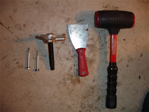
***Warning*** If you are not a patient person and do not feel comfortable doing this task. DONT! Cases are expensive. Take it to the local shop and have them split the cases or you.
***Caution*** I incorporated improvised tooling to split cases. The Puller is not what the Service Manual calls for...but it is a proven method. Proceed at your own risk.
Tooling needed:
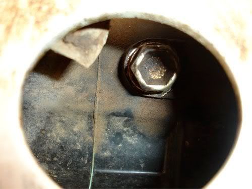
Prep:
Remove all bolts securing cases together. There are some hidden ones....MAKE SURE you get them all removed. One of the hidden bolts.
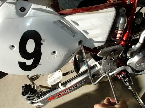
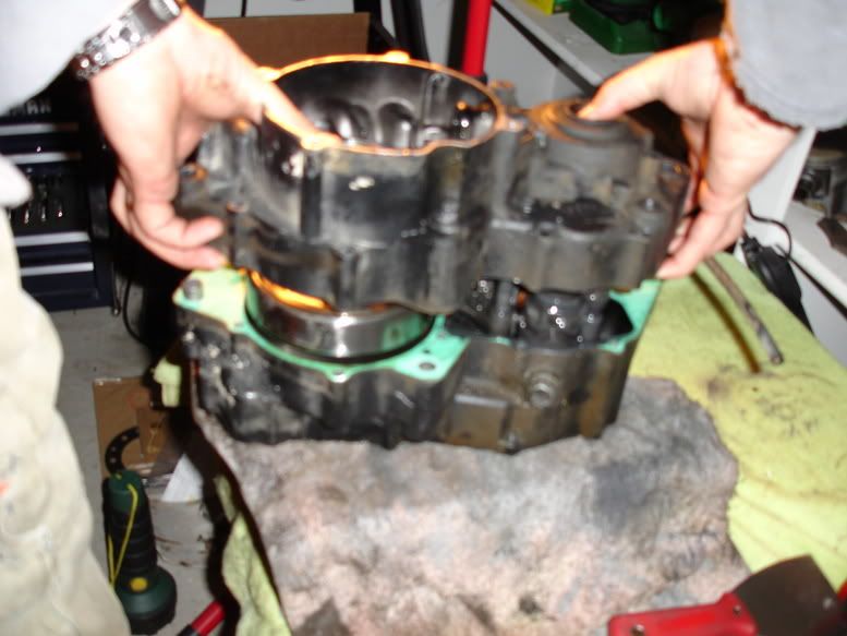
Split em!
First thing you want to do is add a dab of grease to Crank End, left case will be removed first. Next attach Steering Wheel Puller to Left Case via 2 ea bolts.
***Note*** Ensure your bolts are long enough thread fully into Case or risk the possibility of yanking your threads right out of the case. Which will surely ruin your day.
Now apply pressure to Crank via Center bolt/pusher in center of Steering Wheel Puller. Not too tight....just enough to keep constant pressure on crank
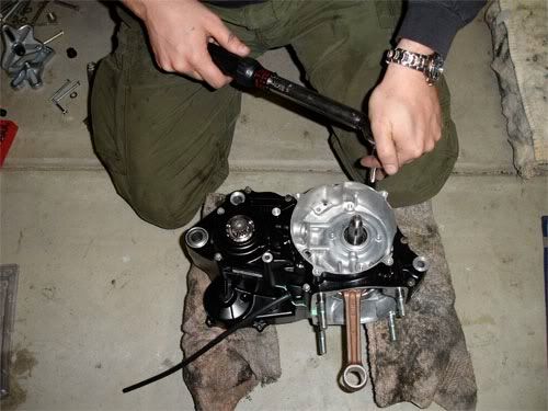
Now take your dead blow mallet and tap on case split lines. After a while the case will loosen up. BE PATIENT!!!!! The Case MUST be removed evenly.....dont cock it. Once a gap is visible in between split-lines...re-tighten up Steering Wheel Puller to pressure on the Crank and repeat. You will be working to get Crank Journal free of Crank Bearing, 2 ea large dowels at front and rear of cases and the Counter-Shaft. Once you have enough of a gap. Start working the spackle knife around the split-line to add in splitting cases. NO SCREWDRIVERS!!!! You will dork up your mating surfaces.
Keep working a combination of the Spackle Knife, Dead Blow and tension on crank end. Take your time.....not a race. Soon enough you will be cleared of Dowels, Crank Bearings and Counter-Shaft.
Remove Left Case.
***Proceed to next section for Tranny removal then return here for Right Case removal.
Right Case removal:
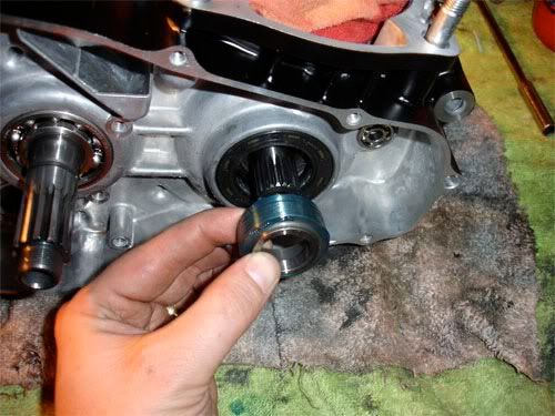
You will again use Steering Wheel Puller to gently push Crank free of Crank Bearing.
Also remove Seal Collar off crank. If it has grooves like this, replace it.
***Note*** There are 2 ea Dowels 180 dgree's out from each other in the cases. If they are trashed...replaced them....cheap. If they loose in the case....bag them up.
Once Crank is free you can inspect the Crank in accordance with Service Manual and ensure it is still "true" and serviceable before re-using.
Crank Inspection:
Inspect the Inner Diameter of Connecting Rod Small End. Example for 85-91, the Inner Diameter shall not exceed 0.9852 inch. If it does, you need a new Connecting Rod
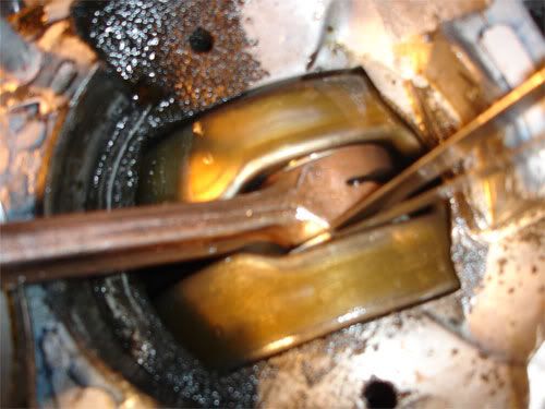
With a Feeler Gauge, measure the side clearance between Connecting Rod big end and Crank Counter-Weight.
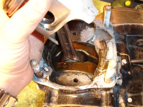
This Crank is bad at 0.048 Service Manual calls for Crank replacement, its can be rebuilt considering your Crank Journals are good as well as everything else.
Unless you have Dial Indicators that are professionally calibrated.....the rest of the Crank Inspection should be accomplished by a machinist. The same person that will tell you if your Crank is still true.
Inspections to determine Crank serviceability:
1) Con-Rod Big end Axial (up and down) Play
2) Crankshaft Runout
3) Inspect Journal Diameter
Case Insp:
First, you will want to remove all old gasket material. Some of it will be very difficult to removed. Soak the stubborn old gaskets with Chem Tool...saturate it and let it sit. After 15 minutes or so it will come right off. Do not use a razor or a screwdriver....could risk the chance of dorking up your mating surfaces.
Now inspect both cases for any obvious damage, cracks (dont confuse with casting marks), damage to sealing surfaces. If there are surface imperfections or deep scratches on the mating surfaces that could hinder a good seal, you can dress them up with swiss files or an oil-stone. One area prone to cracking is the Kickstart Spindle Housing...its likes to fatigue then crack all the way off.
Trash all seals still in cases.....use new seals......unless your el cheapo and re-use toilet paper too....then knock yourself out.
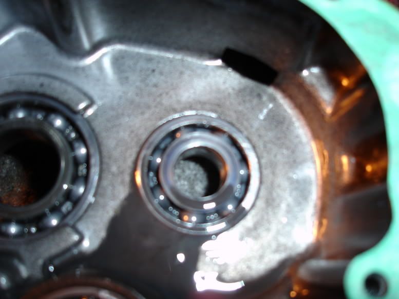
If its been a few years since you've been in your bottom end...replace your Crank Bearings. You could go the same route and replace all Tranny Bearings as well....you would do well to do so.
But you can inspect your Tranny Bearings. With light finger pressure on any bearings' inner race.....turn the bearing. It should move easily and be near silent. If it feels like there is grit in the bearing and it turns like crap and or its noisy....REPLACE it!
You will also need to inspect any bearing bores for wear and such.
Stress/Fatigue and Metal Fracuring:
http://en.wikipedia.org/wiki/Fatigue_(material)
Bearing Failures and what to look for. A very good read and will make you want to change your bearings. 80% of all bearings in the CR500 are Thrust Ball Bearings, others are needle and tapered.
http://www.alliedbearings.com/downloads ... causes.pdf
***Caution*** I incorporated improvised tooling to split cases. The Puller is not what the Service Manual calls for...but it is a proven method. Proceed at your own risk.
Tooling needed:
Prep:
Remove all bolts securing cases together. There are some hidden ones....MAKE SURE you get them all removed. One of the hidden bolts.
Split em!
First thing you want to do is add a dab of grease to Crank End, left case will be removed first. Next attach Steering Wheel Puller to Left Case via 2 ea bolts.
***Note*** Ensure your bolts are long enough thread fully into Case or risk the possibility of yanking your threads right out of the case. Which will surely ruin your day.
Now apply pressure to Crank via Center bolt/pusher in center of Steering Wheel Puller. Not too tight....just enough to keep constant pressure on crank
Now take your dead blow mallet and tap on case split lines. After a while the case will loosen up. BE PATIENT!!!!! The Case MUST be removed evenly.....dont cock it. Once a gap is visible in between split-lines...re-tighten up Steering Wheel Puller to pressure on the Crank and repeat. You will be working to get Crank Journal free of Crank Bearing, 2 ea large dowels at front and rear of cases and the Counter-Shaft. Once you have enough of a gap. Start working the spackle knife around the split-line to add in splitting cases. NO SCREWDRIVERS!!!! You will dork up your mating surfaces.
Keep working a combination of the Spackle Knife, Dead Blow and tension on crank end. Take your time.....not a race. Soon enough you will be cleared of Dowels, Crank Bearings and Counter-Shaft.
Remove Left Case.
***Proceed to next section for Tranny removal then return here for Right Case removal.
Right Case removal:
You will again use Steering Wheel Puller to gently push Crank free of Crank Bearing.
Also remove Seal Collar off crank. If it has grooves like this, replace it.
***Note*** There are 2 ea Dowels 180 dgree's out from each other in the cases. If they are trashed...replaced them....cheap. If they loose in the case....bag them up.
Once Crank is free you can inspect the Crank in accordance with Service Manual and ensure it is still "true" and serviceable before re-using.
Crank Inspection:
Inspect the Inner Diameter of Connecting Rod Small End. Example for 85-91, the Inner Diameter shall not exceed 0.9852 inch. If it does, you need a new Connecting Rod
With a Feeler Gauge, measure the side clearance between Connecting Rod big end and Crank Counter-Weight.
This Crank is bad at 0.048
Unless you have Dial Indicators that are professionally calibrated.....the rest of the Crank Inspection should be accomplished by a machinist. The same person that will tell you if your Crank is still true.
Inspections to determine Crank serviceability:
1) Con-Rod Big end Axial (up and down) Play
2) Crankshaft Runout
3) Inspect Journal Diameter
Case Insp:
First, you will want to remove all old gasket material. Some of it will be very difficult to removed. Soak the stubborn old gaskets with Chem Tool...saturate it and let it sit. After 15 minutes or so it will come right off. Do not use a razor or a screwdriver....could risk the chance of dorking up your mating surfaces.
Now inspect both cases for any obvious damage, cracks (dont confuse with casting marks), damage to sealing surfaces. If there are surface imperfections or deep scratches on the mating surfaces that could hinder a good seal, you can dress them up with swiss files or an oil-stone. One area prone to cracking is the Kickstart Spindle Housing...its likes to fatigue then crack all the way off.
Trash all seals still in cases.....use new seals......unless your el cheapo and re-use toilet paper too....then knock yourself out.
If its been a few years since you've been in your bottom end...replace your Crank Bearings. You could go the same route and replace all Tranny Bearings as well....you would do well to do so.
But you can inspect your Tranny Bearings. With light finger pressure on any bearings' inner race.....turn the bearing. It should move easily and be near silent. If it feels like there is grit in the bearing and it turns like crap and or its noisy....REPLACE it!
You will also need to inspect any bearing bores for wear and such.
Stress/Fatigue and Metal Fracuring:
http://en.wikipedia.org/wiki/Fatigue_(material)
Bearing Failures and what to look for. A very good read and will make you want to change your bearings. 80% of all bearings in the CR500 are Thrust Ball Bearings, others are needle and tapered.
http://www.alliedbearings.com/downloads ... causes.pdf
Last edited by Rosco-Peeko on April 2nd, 2010, 9:37 pm, edited 2 times in total.
Somewhere in Kenya, a village is missing their idiot.......
-
Rosco-Peeko
- Posts: 823
- Joined: June 1st, 2007, 2:47 pm
Part VI Tranny Removal
***Note*** If you noticed my crank is not there during this step.....that was due to hi-tech slip fit crank and bearings.....my old cases were cool like that.
Prep:
You will need some rubber bands, old towel and patience...proceed.
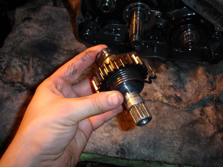
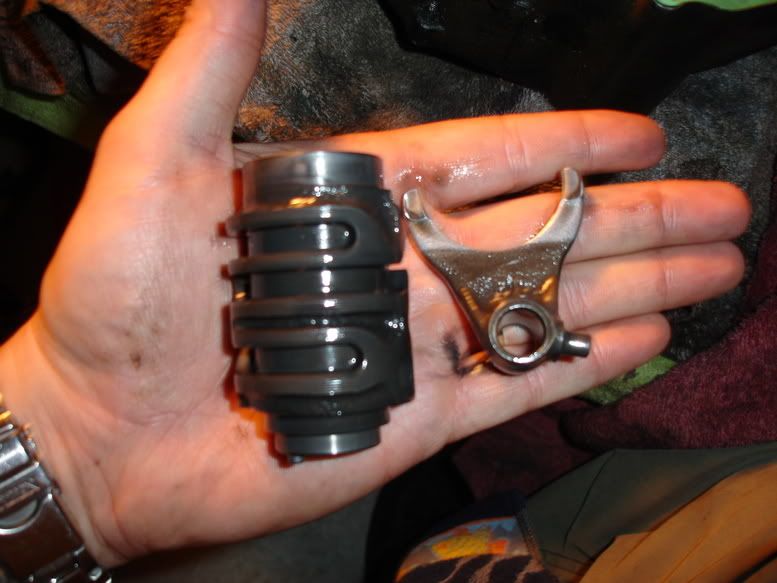
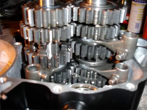
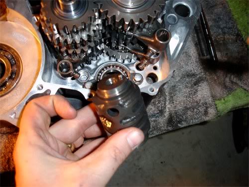
Shift Forks, Shafts and Shift Drum removal:
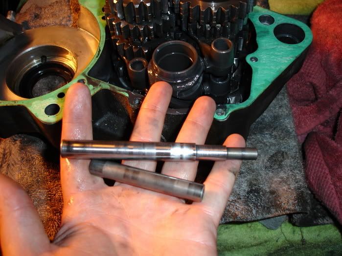
Pull your two Shift Fork Shafts out..
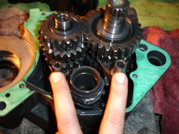
Note the different sizes....its Murphy-Proof to get them confused.
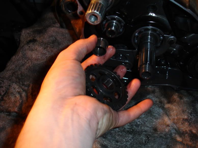
Slide Shift Forks out of Shift Drum...the dowels.
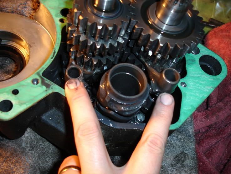
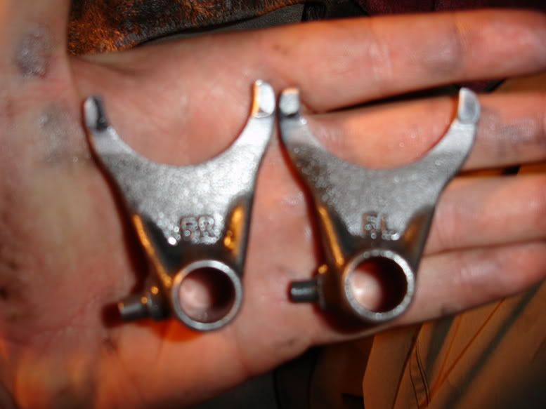
Remove Shift Forks....except for 5C or the forward most Shift Fork. Its easier to pull it out when the Shift Drum is removed. Not they say 5R and 5L, those are locations. As if you were sitting on the bike and looking down at the motor....make sense?
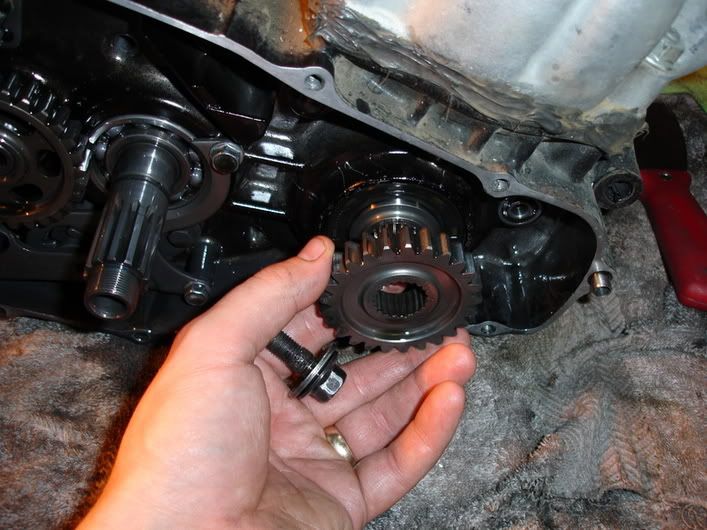
Wiggle Shift Drum until its free....remove Shift Fork 5C as well.
A word of caution before we proceed. See these seemingly harmless washers? They are Thrust Washers. They go in specific locations according to thickness. Many of hoons have had problems with their tranny not shifting correctly from getting the washers in the wrongs sport and throwing tolerances off. Be cognizant of them.
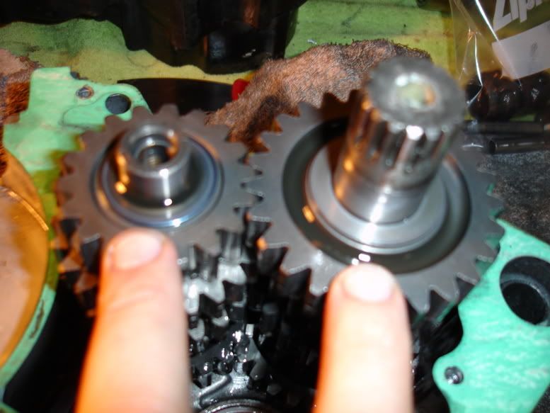
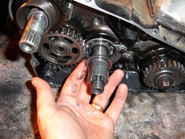
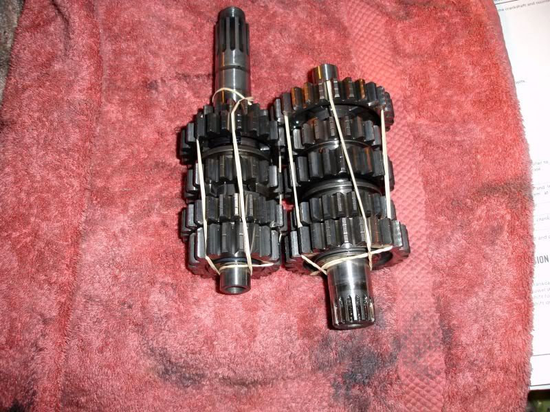
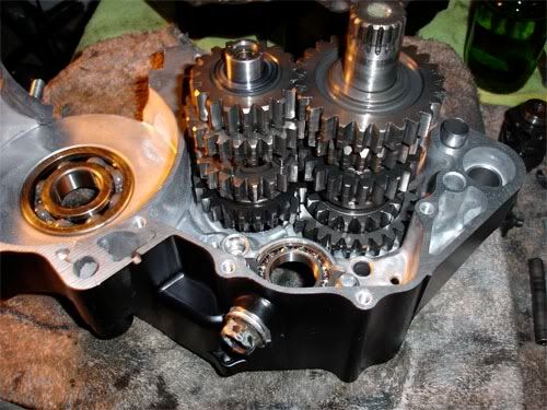
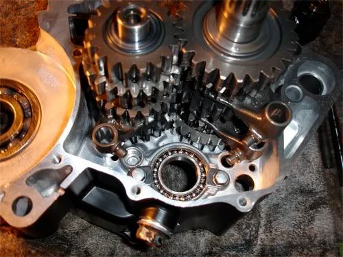
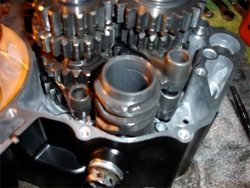
Mainshaft and Countershaft removal:
This is not that bad....but it is best to wiggle your fingers under the gears sitting against the right case and pull both assemblies up together. It can be tricky but is the best way to do it. Remove.....them now.
HEY! What is that? Is that a bearing or a Thrust Washer for the Countershaft?
It was a Thrust Washer!! Simple mistakes like this make big headaches later. The smaller Thrust Washers like to stick to the bearings via oil.
Once you have everything, wrap rubber-bands around the tranny ends to keep everything in place. Then wrap in a towel to protect your gears until your ready to inspect them.
Prep:
You will need some rubber bands, old towel and patience...proceed.
Shift Forks, Shafts and Shift Drum removal:
Pull your two Shift Fork Shafts out..
Note the different sizes....its Murphy-Proof to get them confused.
Slide Shift Forks out of Shift Drum...the dowels.
Remove Shift Forks....except for 5C or the forward most Shift Fork. Its easier to pull it out when the Shift Drum is removed. Not they say 5R and 5L, those are locations. As if you were sitting on the bike and looking down at the motor....make sense?
Wiggle Shift Drum until its free....remove Shift Fork 5C as well.
A word of caution before we proceed. See these seemingly harmless washers? They are Thrust Washers. They go in specific locations according to thickness. Many of hoons have had problems with their tranny not shifting correctly from getting the washers in the wrongs sport and throwing tolerances off. Be cognizant of them.
Mainshaft and Countershaft removal:
This is not that bad....but it is best to wiggle your fingers under the gears sitting against the right case and pull both assemblies up together. It can be tricky but is the best way to do it. Remove.....them now.
HEY! What is that? Is that a bearing or a Thrust Washer for the Countershaft?
It was a Thrust Washer!! Simple mistakes like this make big headaches later. The smaller Thrust Washers like to stick to the bearings via oil.
Once you have everything, wrap rubber-bands around the tranny ends to keep everything in place. Then wrap in a towel to protect your gears until your ready to inspect them.
Somewhere in Kenya, a village is missing their idiot.......
-
Rosco-Peeko
- Posts: 823
- Joined: June 1st, 2007, 2:47 pm
Part VIII Tranny/Crank Install
Right Case Build Up:
If you have come this far, your Crank is within spec, all bearings are good and you have new seals standing by....
Your crap should look like this:
Lube er up:
Douche your Crank Bearings with a bit of your Premix Oil of choice. Work it in by turning inner race.
Juice up ALL of your Tranny Bearings with your Tranny Fluid of choice. Work it in.....
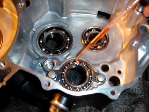
Question: So why pre-lube them thar Bearings?
Answer: It ensures your bearing are lubed prior to the first start = longevity.
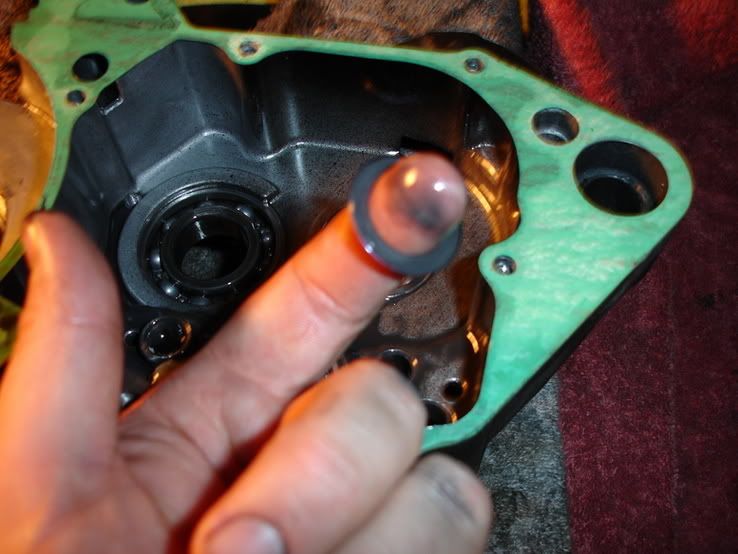
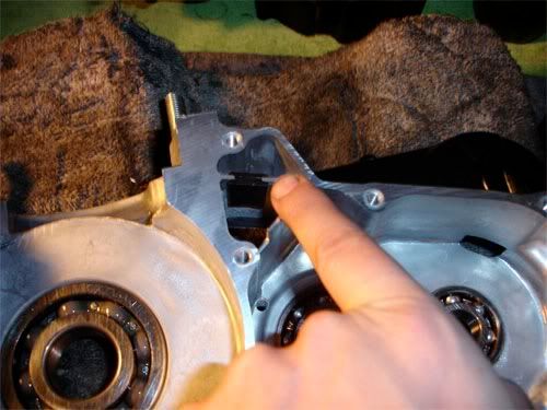
Slide the rubber chingus in over the breather area. This is important unless you like your breather tube pukin tranny fluid out. A simple step to forget but an important one.
Tranny Install:
***Note***Put Right Case on two different blocks of wood of equal height. This will help with clearance issues of Crank and Mainshaft.
Be patient on this step!! It is best to drop both the Mainshaft and Countershaft in at the same time. THIS IS the easiest way Please make sure all of your Thrust Washers are present and in the correct places...or you are in for a bitchin headache. "But, Rob...its hard to drop them in at the same time and I loose skin off my fingers..." Suck it up buttercup, repeat till you get it right...both will drop in at the same time...hold gears and wiggle em a bit to mesh gears and they will drop in.
Slide your Shift Forks into appropriate spots...5C is forward (mainshaft). Then put in 5R...closest to case and then 5L...both are on Counter Shaft. You will want to swing them out to make room for Shift Drum install:
Shift Drum install:
The shift drum is a tight/machined fit in the case. Wiggle it in and ensure its seated fully before proceeding.
Slide your Shift Fork's inward into shift drum into appropriate slots on Shift Drum....fool proof. You may need to pick up the forks/gears and slide them in. Work Shift Drum fully to the right and left while spinning Countershaft. Do NOT proceed unless you can accomplish this.
Lets test your work. Without the crank or any gaskets. Install Right Case. Attempt to tun the Countershaft. You should feel only the friction of the Tranny Gears!!!! If it is unreasonably tight or hard to turn, something is amiss!!! Do not proceed until you have fixed the problem!
Ensure both Dowels are installed. If you are this far down....hopefully you spent the $0.89 on two new Dowels....sorry no pic.
Crank Install:
If its late at night....cover the cases. Put your Crank inside a large ziplock....smoosh all the air out. Insert inside of another large ziplock for moisture control. Put it in freezer. Let it sit overnight. This will cool the crank obviously and shrink your Crank Journals. Remember cold contracts and heat expands.
If Corrosion is a major concern for you and you have access to Dry Ice...this would be 10X better!!!!!! Chill Journals for 1 hour while keeping them insulated to super cool them and make the most of your Dry Ice.
***Note***This method is proven. I have duplicated this numerous times as have others. Time is of the essence...you need to work at an accelerated tempo when working with heated and cooled parts. This method resembles the same to install a Low Pressure Turbine into a High Pressure Turbine on a F110-GE-110/129 Jet Engine....it works. If you are concerned about lateral loading of bearings. This will mostly eliminate that....not that it really matters. Crank Bearings are Thrust Bearings = can accept radial and lateral loads.....
Install Case Gasket and trim with razor as necessary. Remove all gasket bits...
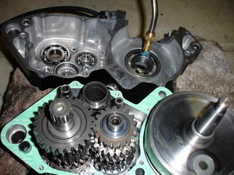
Pull Crank from freezer or dust off dry ice from appropriate crank journal (careful, dry ice is so cold it will burn the shit out of your bare skin!!). Take a BernzoMatic and heat the Right Case Crank Bearing Inner Race (ONLY!!!!...not the balls....not the Outer Race...just what the Crank Journal seats into) Hit it with high heat for in a circular motion to heat the whole inner race for 30 seconds. Remove heat and carefully drop Crank into Crank Bearing...should slide right in and seat easily! No pic sorry...was in a hurry.
***Note*** Dont Forget to install your Breather Tube and "New" Dowel Pins!!!
Now repeat with Left Case Crank Bearing.....dust off ice...30 seconds of heat. The Drop Left Case on EVENLY!!!!! it should seat...may need a bit of wiggling. If you stick it for being too slow....DO NOT USE MALLET!!!!!! Use Puller and re-freeze/heat accordingly!!!!!!!! Then do it again.
Install Clean Case bolts and torque in a star pattern IAW Service Manual:
Stuff a CLEAN shop rag around your Connecting Rod to protect it and to keep FO (horseshit) from fallin in bottom end = bad.
Take a break and have a beer....Good job man-o!!!!!
If you have come this far, your Crank is within spec, all bearings are good and you have new seals standing by....
Your crap should look like this:
Lube er up:
Douche your Crank Bearings with a bit of your Premix Oil of choice. Work it in by turning inner race.
Juice up ALL of your Tranny Bearings with your Tranny Fluid of choice. Work it in.....
Question: So why pre-lube them thar Bearings?
Answer: It ensures your bearing are lubed prior to the first start = longevity.
Slide the rubber chingus in over the breather area. This is important unless you like your breather tube pukin tranny fluid out. A simple step to forget but an important one.
Tranny Install:
***Note***Put Right Case on two different blocks of wood of equal height. This will help with clearance issues of Crank and Mainshaft.
Be patient on this step!! It is best to drop both the Mainshaft and Countershaft in at the same time. THIS IS the easiest way Please make sure all of your Thrust Washers are present and in the correct places...or you are in for a bitchin headache. "But, Rob...its hard to drop them in at the same time and I loose skin off my fingers..." Suck it up buttercup, repeat till you get it right...both will drop in at the same time...hold gears and wiggle em a bit to mesh gears and they will drop in.
Slide your Shift Forks into appropriate spots...5C is forward (mainshaft). Then put in 5R...closest to case and then 5L...both are on Counter Shaft. You will want to swing them out to make room for Shift Drum install:
Shift Drum install:
The shift drum is a tight/machined fit in the case. Wiggle it in and ensure its seated fully before proceeding.
Slide your Shift Fork's inward into shift drum into appropriate slots on Shift Drum....fool proof. You may need to pick up the forks/gears and slide them in. Work Shift Drum fully to the right and left while spinning Countershaft. Do NOT proceed unless you can accomplish this.
Lets test your work. Without the crank or any gaskets. Install Right Case. Attempt to tun the Countershaft. You should feel only the friction of the Tranny Gears!!!! If it is unreasonably tight or hard to turn, something is amiss!!! Do not proceed until you have fixed the problem!
Ensure both Dowels are installed. If you are this far down....hopefully you spent the $0.89 on two new Dowels....sorry no pic.
Crank Install:
If its late at night....cover the cases. Put your Crank inside a large ziplock....smoosh all the air out. Insert inside of another large ziplock for moisture control. Put it in freezer. Let it sit overnight. This will cool the crank obviously and shrink your Crank Journals. Remember cold contracts and heat expands.
If Corrosion is a major concern for you and you have access to Dry Ice...this would be 10X better!!!!!! Chill Journals for 1 hour while keeping them insulated to super cool them and make the most of your Dry Ice.
***Note***This method is proven. I have duplicated this numerous times as have others. Time is of the essence...you need to work at an accelerated tempo when working with heated and cooled parts. This method resembles the same to install a Low Pressure Turbine into a High Pressure Turbine on a F110-GE-110/129 Jet Engine....it works. If you are concerned about lateral loading of bearings. This will mostly eliminate that....not that it really matters. Crank Bearings are Thrust Bearings = can accept radial and lateral loads.....
Install Case Gasket and trim with razor as necessary. Remove all gasket bits...
Pull Crank from freezer or dust off dry ice from appropriate crank journal (careful, dry ice is so cold it will burn the shit out of your bare skin!!). Take a BernzoMatic and heat the Right Case Crank Bearing Inner Race (ONLY!!!!...not the balls....not the Outer Race...just what the Crank Journal seats into) Hit it with high heat for in a circular motion to heat the whole inner race for 30 seconds. Remove heat and carefully drop Crank into Crank Bearing...should slide right in and seat easily! No pic sorry...was in a hurry.
***Note*** Dont Forget to install your Breather Tube and "New" Dowel Pins!!!
Now repeat with Left Case Crank Bearing.....dust off ice...30 seconds of heat. The Drop Left Case on EVENLY!!!!! it should seat...may need a bit of wiggling. If you stick it for being too slow....DO NOT USE MALLET!!!!!! Use Puller and re-freeze/heat accordingly!!!!!!!! Then do it again.
Install Clean Case bolts and torque in a star pattern IAW Service Manual:
Stuff a CLEAN shop rag around your Connecting Rod to protect it and to keep FO (horseshit) from fallin in bottom end = bad.
Take a break and have a beer....Good job man-o!!!!!
Somewhere in Kenya, a village is missing their idiot.......
-
Rosco-Peeko
- Posts: 823
- Joined: June 1st, 2007, 2:47 pm
Part IX Seals Install
Precursor: I hope if you have came this far you have replaced all of your seals. I am a fan of OEM Honda Seals, they are the best IMHO and come are pre-lubed! Use what you like but replace all old seals...dont be a cheap-skate!
1) Clean Counter-Shaft Collar and lube up rubber sealing ring (looks like a flat o-ring) with grease and install.
2) Install Clutch Actuation Arm Seal....note if you have a tranny leak in this area...replace this seal...future reference stuff.
3) Install seal for Shifter Spindle...I grease it up real nice so there is less of a chance of chopping/cutting it when installing Shifter Linkage.
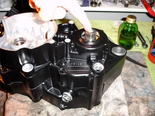
4) Right Crank Seal, get it started evenly then use a drift and tap it in using a star pattern. Go in EVENLY! Drive it in till its even with housing.
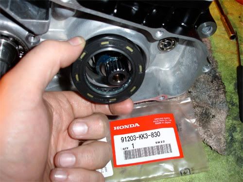
The install Seal Collar:
5) Left Crank Seal...tricky...kinda...sorry no pic.
a) Wrap crank end around Woodruff Key with Masking Tape to prevent cutting seal during installation.
b) Lube/grease things up and slide it on.
c) Use drift and lightly tap around outside in star pattern till seated in bore.
d) remove tap and clean up excess lube/grease.
1) Clean Counter-Shaft Collar and lube up rubber sealing ring (looks like a flat o-ring) with grease and install.
2) Install Clutch Actuation Arm Seal....note if you have a tranny leak in this area...replace this seal...future reference stuff.
3) Install seal for Shifter Spindle...I grease it up real nice so there is less of a chance of chopping/cutting it when installing Shifter Linkage.
4) Right Crank Seal, get it started evenly then use a drift and tap it in using a star pattern. Go in EVENLY! Drive it in till its even with housing.
The install Seal Collar:
5) Left Crank Seal...tricky...kinda...sorry no pic.
a) Wrap crank end around Woodruff Key with Masking Tape to prevent cutting seal during installation.
b) Lube/grease things up and slide it on.
c) Use drift and lightly tap around outside in star pattern till seated in bore.
d) remove tap and clean up excess lube/grease.
Somewhere in Kenya, a village is missing their idiot.......
-
Rosco-Peeko
- Posts: 823
- Joined: June 1st, 2007, 2:47 pm
Part X Shift Linkage, Clutch, Idler Gear, Primary Gear...Etc
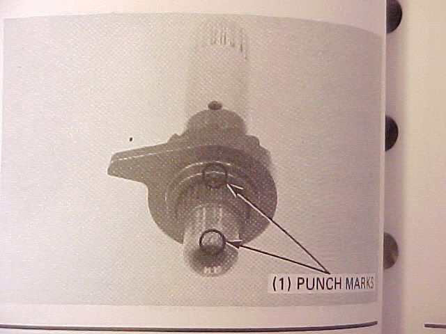
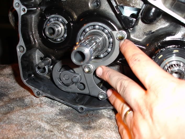
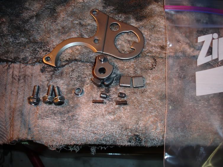
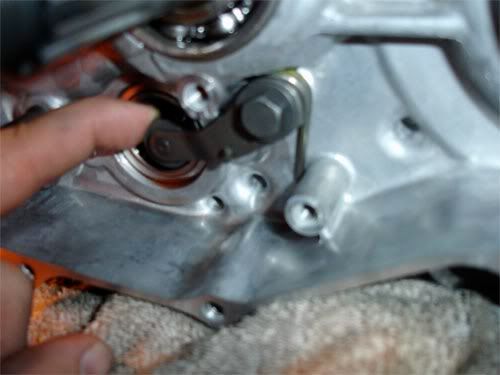
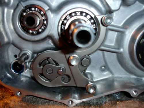
Stopper Arm/Drum Center Install:
1) Install Stopper Arm, Spring, Washer and Bolt. Ensure Washer is on head side of bolt and the spring is installed correctly. You should feel resistance from the spring while pushing down on arm. Should look like this:
2) Drum Center...can be a bit tricky. Notice locator dowel on Shift Drum...yes yes.....flip Drum Center over and you will see a notch machined specifically for the locator dowel on the shift drum.
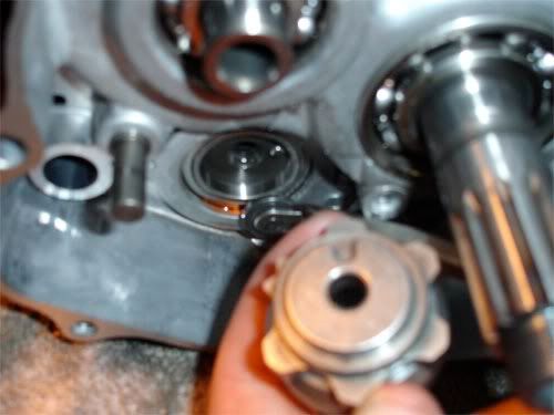
Using a Screwstik (long flat head screwdriver) pry down on Stopper Arm to facilitate enough room to install Drum Center to the back of the Shift Drum. This is a machined fit...MAKE SURE ITS COMPLETELY FLUSH and dowel's are lined up before installing center bolt!!!
Install center bolt with locking agent (Blue Loctite) and torque to spec....
Guide Plate Build up and Install:
***Work over a table while performing this task! There are too many small parts to loose under spring pressure. If not, have one of your plungers shoot across the room....you will have a full understanding of the term, "Sweating like a whore in Church" as surely the Honda Shop does not have them readily in stock***
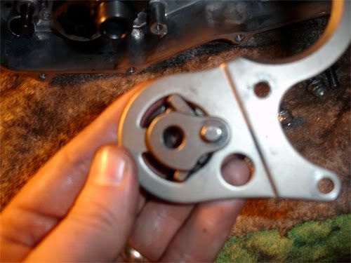
1) Get your Drum Shifter:
2) Install springs into holes and then put plungers over springs....looks like this:
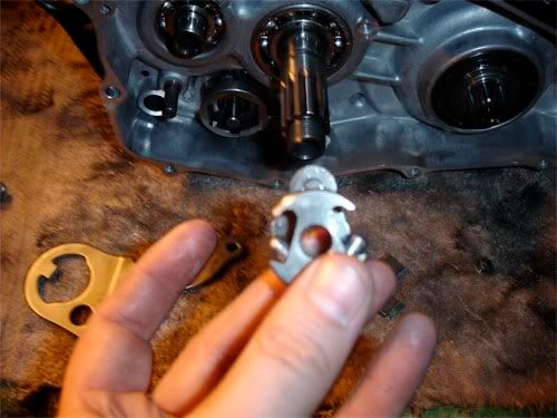
3) Install Ratchet Pawls into cut outs and over Plungers.
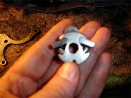
4) Compress Pawls onto Plungers/Springs (Squeeze it together man) and install into Guide Plate. Sometimes it take a few tries..others it does not....dont get discouraged. Once in everything is in place....gently hold it there.
Using socket set-up, turn Drum Center to put Tranny in any gear other than neutral.
5) Install Guide Plate. You may need to Squeeze the Ratchet Pawls in a hair to get the to line up/compress enough to engage the Drum Center cut-outs. Tighten 3 each Guide Plate mounting bolts.
6) Hey! Dont forget the Shift Collar.
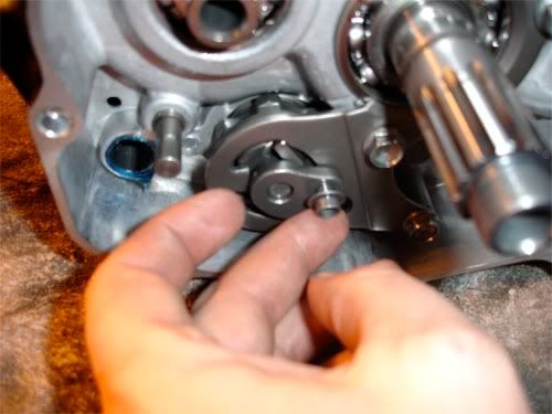
Shift Spindle Install:
Slide Shift Spindle into place.....make sure you have your washer...
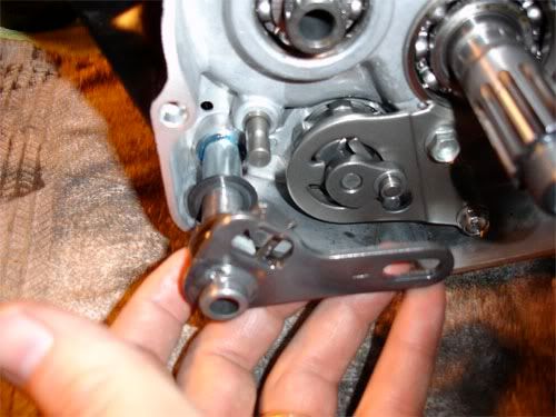
Upper Cut Out through stationary stud, the other on the Shift Collar....like so:
In-Progress.....
1) Install Stopper Arm, Spring, Washer and Bolt. Ensure Washer is on head side of bolt and the spring is installed correctly. You should feel resistance from the spring while pushing down on arm. Should look like this:
2) Drum Center...can be a bit tricky. Notice locator dowel on Shift Drum...yes yes.....flip Drum Center over and you will see a notch machined specifically for the locator dowel on the shift drum.
Using a Screwstik (long flat head screwdriver) pry down on Stopper Arm to facilitate enough room to install Drum Center to the back of the Shift Drum. This is a machined fit...MAKE SURE ITS COMPLETELY FLUSH and dowel's are lined up before installing center bolt!!!
Install center bolt with locking agent (Blue Loctite) and torque to spec....
Guide Plate Build up and Install:
***Work over a table while performing this task! There are too many small parts to loose under spring pressure. If not, have one of your plungers shoot across the room....you will have a full understanding of the term, "Sweating like a whore in Church" as surely the Honda Shop does not have them readily in stock***
1) Get your Drum Shifter:
2) Install springs into holes and then put plungers over springs....looks like this:
3) Install Ratchet Pawls into cut outs and over Plungers.
4) Compress Pawls onto Plungers/Springs (Squeeze it together man) and install into Guide Plate. Sometimes it take a few tries..others it does not....dont get discouraged. Once in everything is in place....gently hold it there.
Using socket set-up, turn Drum Center to put Tranny in any gear other than neutral.
5) Install Guide Plate. You may need to Squeeze the Ratchet Pawls in a hair to get the to line up/compress enough to engage the Drum Center cut-outs. Tighten 3 each Guide Plate mounting bolts.
6) Hey! Dont forget the Shift Collar.
Shift Spindle Install:
Slide Shift Spindle into place.....make sure you have your washer...
Upper Cut Out through stationary stud, the other on the Shift Collar....like so:
In-Progress.....
Somewhere in Kenya, a village is missing their idiot.......