CR500 Engine Build Pictorial Part 5 (Final Installment)

All Engine, Clutch, Chains, and Sprockets Stuff Here.
Post Reply
dogger315
Posts: 87
Joined: March 14th, 2010, 2:41 pm

CR500 Engine Build Pictorial Part 5 (Final Installment)

Post by dogger315 »

This is the final section of the build. I will cover cylinder and head
installation and finish with the intake and carburetor.

Squirt some clean two stroke oil into the ring landings of the piston.
Carefully spread the rings and install with the mark facing up and the
gap centered on the pin.
Image
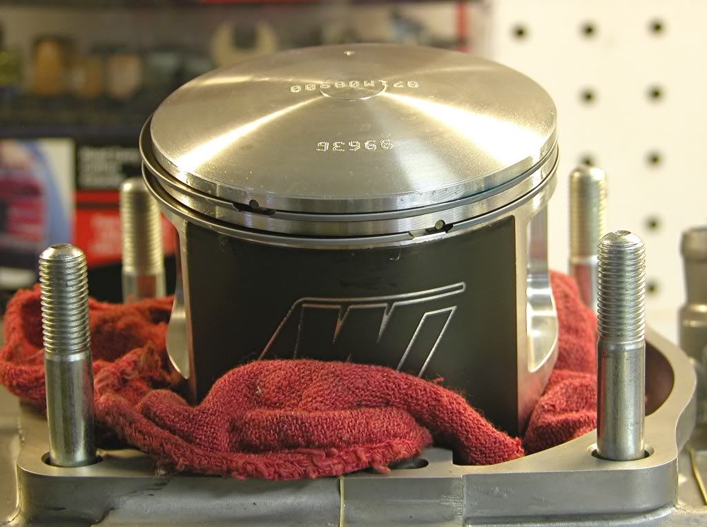
Install the two allignment dowels on the left side cylinder studs.
Image
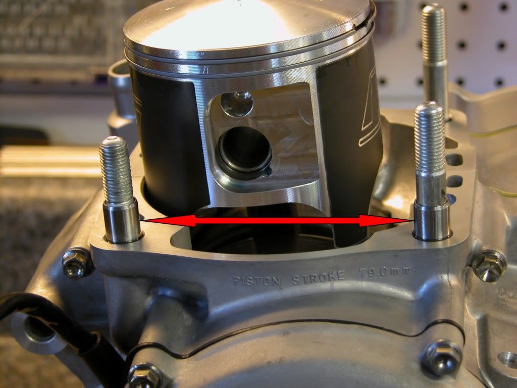
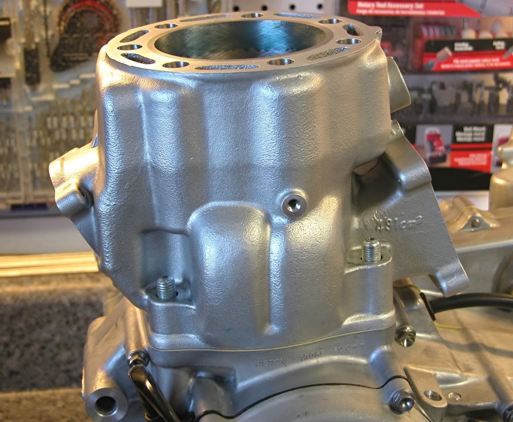
Place a new base gasket on the crankcase and carefully lower the cylinder
over the compressed rings until seated on the crankcase. Be careful not
to rotate the cylinder during this process because it is possible to snag and
break a ring.
Image
Place several drops of oil on the landings and apply anti seize to the cylinder
studs.
Image
Install the four flange nuts and using a torque extension tool, torque the
nuts to 29 lbft in three steps and in a criss cross pattern.
Image
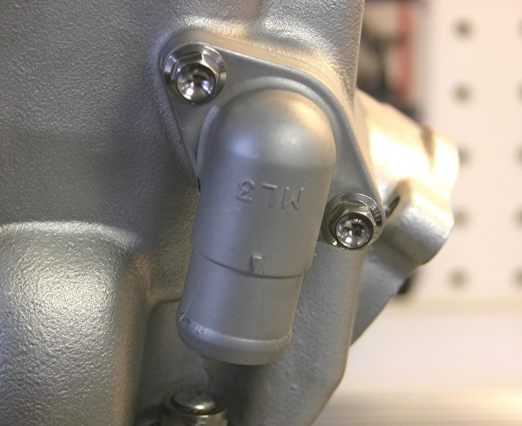
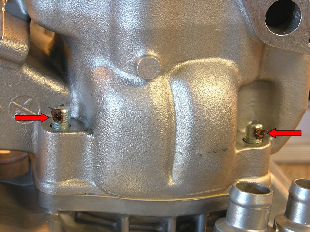
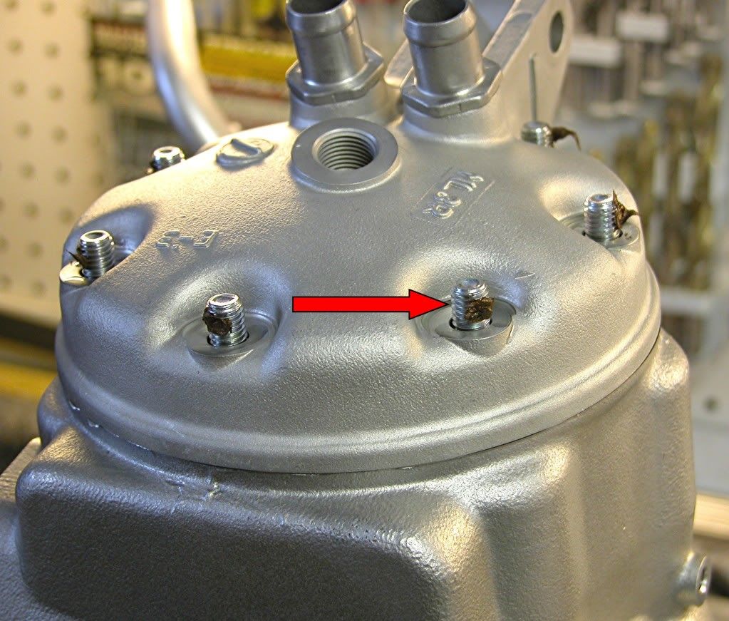
Install the coolant drain bolt into the left side of the cylinder using a new
copper washer and torque to 7 lbft. Install the exhaust flange using a new
gasket and torque the bolts to 7 lbft.
Image
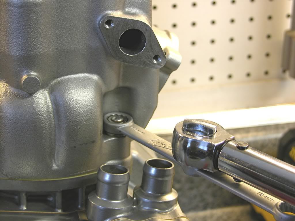
Place a new O-ring in the water hose joint.
Image
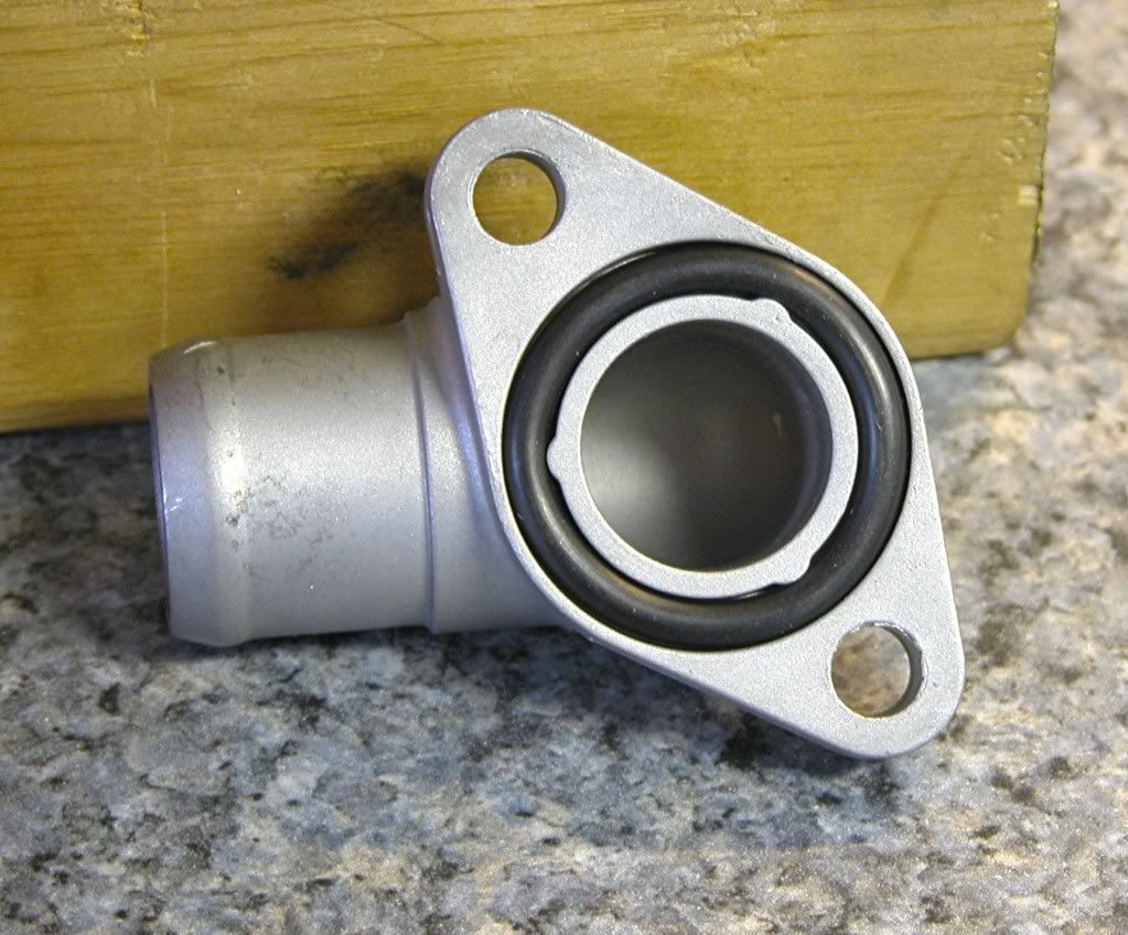
Install the joint to the right side of the cylinder. Torque the bolts to 7 lbft.
Image
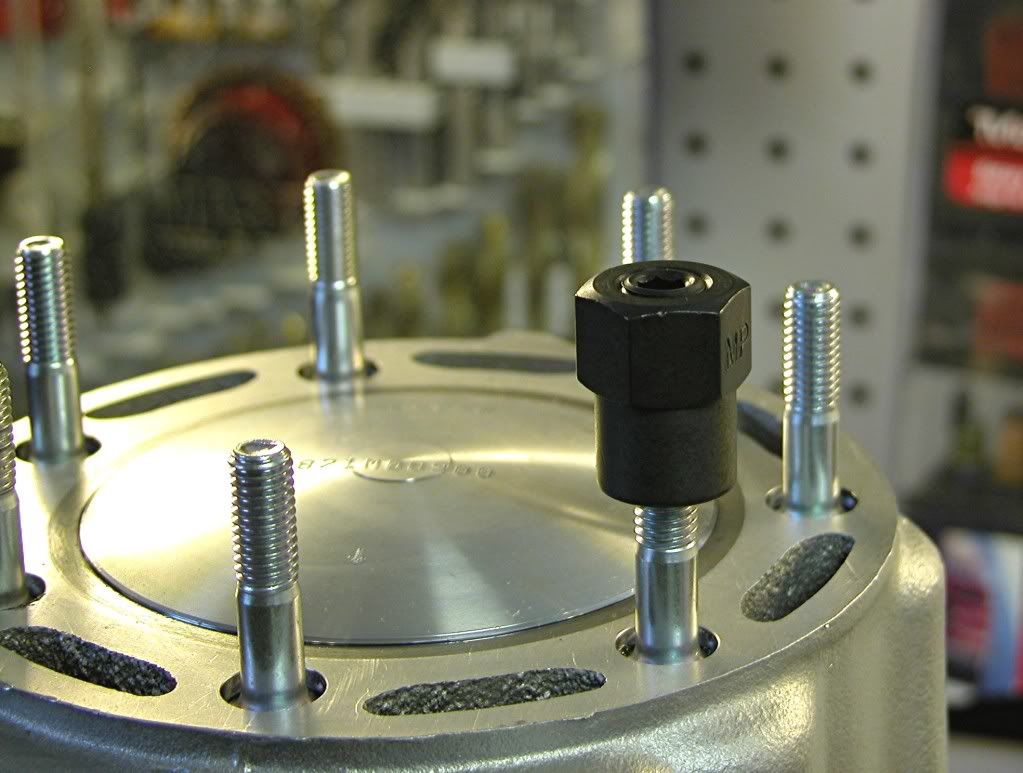
Install the seven cylinder head studs into the top of the cylinder. Prep the
studs with Blue loctite on the bottom and antiseize higher up on the threads.
Torque the studs to 9 lbft. using oposing flange nuts or a stud installer.
Image
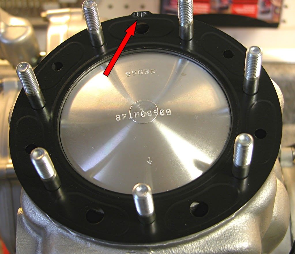
Place a new head gasket with the "UP" mark facing aft onto the cylinder.
Image
Install the cylinder head. Apply several drops of oil to the flange landings
and anti-seize to the threads.
Image
Install the cylinder head flange nuts and torque to 20 lbft in three steps and
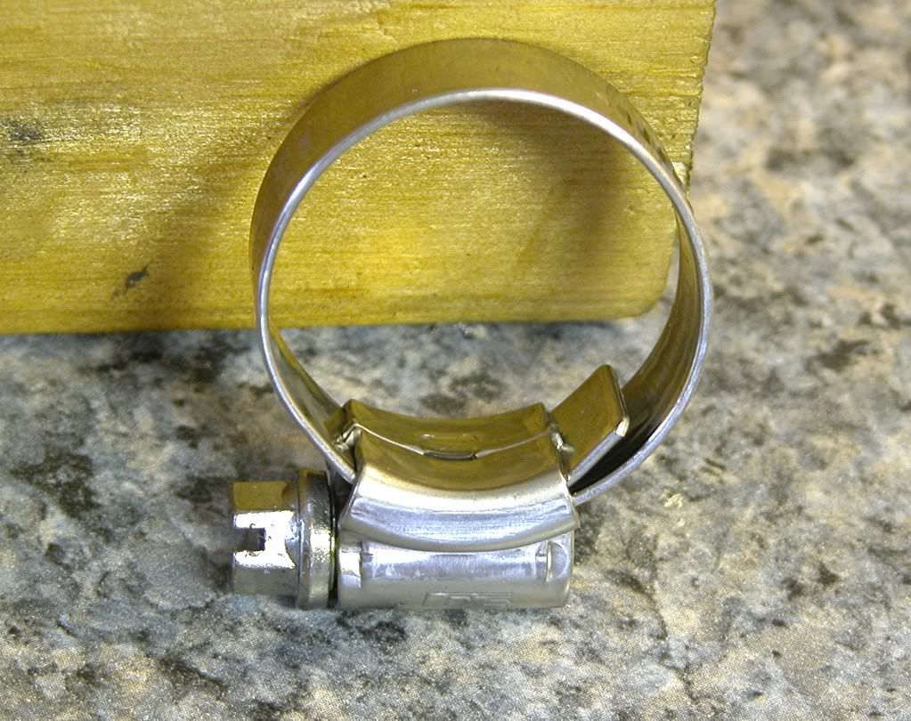
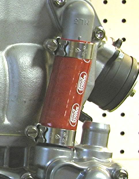
in a criss cross pattern. Next, install the coolant hose. If you use silicon
hose, make sure to use silicon hose specific hose clamps. These clamps
have a smooth surface around the worm gear and beveled edges so they
won't cut the hose like a normal clamp.
Image
Image

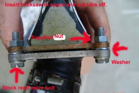
Next up is the intake. I am using a VForce 3 reed valve. This valve requires
the removal of the rubber reed stuffers present on the stock Honda intake.
Image
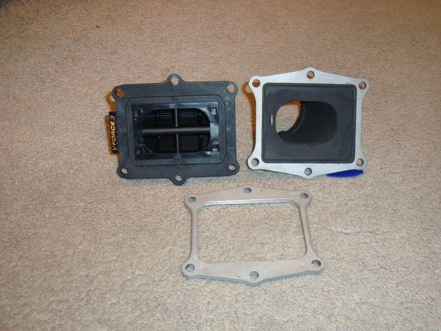
Spray some Blue Permatex gasket adhesive on one of the gaskets included in
the VForce kit and allow it to tack up.
Image
Place the gasket on the intake.
Image
Install the VForce
Image
Use the second included gasket between the VForce reed and the intake
and secure using the six hex flange bolts. Torque the bolts to 6.5 lbft.
Image
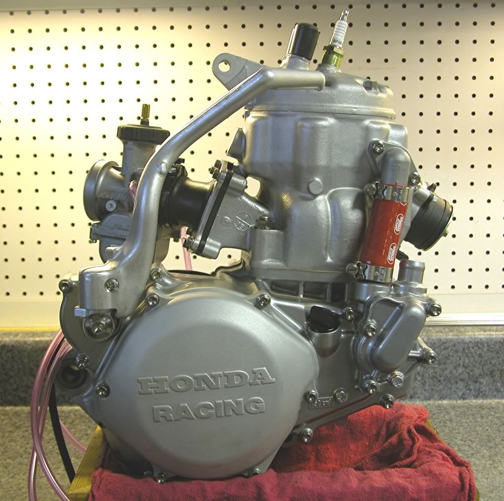
Install the spark plug and perform a leak down test. This is a critical test
that will determine if the engine is air tight for all intents and purposes.
I use a Motion Pro tester and pump the engine to 6 psi before starting
the stop watch. This engine didn't lose any pressure over the 5 minutes
I measured - good enough for me. A pressure loss of 1psi/min is the
maximum you should allow. Any more than that and you will have
problems.

Next install the carburetor, in this case a 39.5mm Keihin PWK, and you are
done.
Image
Image
Image
Image

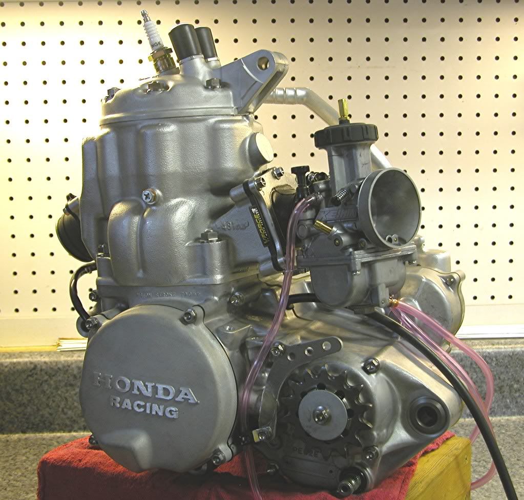
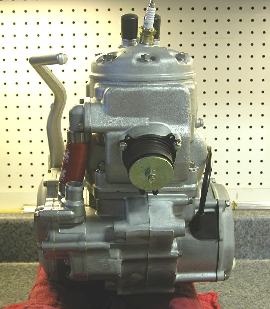
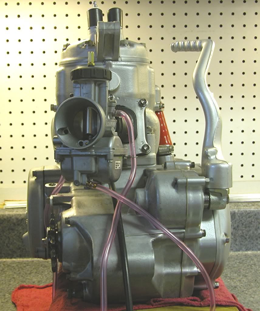
This engine should produce about 70 hp with a smooth useable
powerband.

dogger

--------------------------------------------------------------------------------
User avatar
2strokeforever
Posts: 1524
Joined: November 13th, 2009, 1:04 pm
Location: Vernon B.C Canada

Post by 2strokeforever »

that carb looks new, make sure it didnt come with a CEJ
the 450 will have less power and will be harder to start, and will be heavier, but to make up for it it will require more maintenance.
4stroke=dead fish
dubious01
Posts: 472
Joined: October 23rd, 2009, 1:24 pm
Location: Calgary

Post by dubious01 »

I dont want to criticise cause I know its a bit of work and time, and you have a done a good job, with nice pictures.
stock compression, dome, stock port timing basically, 70 HP at the crank maybe...

Beautiful pictures, and super super clean work.
Last edited by dubious01 on January 15th, 2011, 4:25 pm, edited 1 time in total.
User avatar
2strokeforever
Posts: 1524
Joined: November 13th, 2009, 1:04 pm
Location: Vernon B.C Canada

Post by 2strokeforever »

how much did all the ti cost you, and if you still have all the old steel bolts could you put them in a bucket and weigh them?

ive heard you save more doing the shock linkage and axle bolts ti, and the rest arent worth it
the 450 will have less power and will be harder to start, and will be heavier, but to make up for it it will require more maintenance.
4stroke=dead fish
User avatar
AlisoBob
"Hoon-father"
Posts: 15404
Joined: May 31st, 2007, 6:39 pm
Location: Aliso Viejo Ca

Post by AlisoBob »

Image

More good info!

One thing I do different though is to slide the hose and clamps on first, and then bolt the fitting on.
User avatar
redrocket190
Posts: 1229
Joined: September 17th, 2007, 9:07 pm
Location: San Clemente, CA

Post by redrocket190 »

The dished head bolts do look like Ti, but did you use Ti for non-stressed use? Your vintage restorations lead me to suspect pockets bottomless but this might kill me with envy. Also how did you grind off the stuffers (?) from the stock reed mount to get the V-Force to fit? I'm installing one now and worried about damaging the o-ring type gasket. Awesome build but not a surprise after seeing your previous work over at the Elsinore site...

:cool:
Michael Stiles
2007 Honda CR500R-AF
User avatar
AlisoBob
"Hoon-father"
Posts: 15404
Joined: May 31st, 2007, 6:39 pm
Location: Aliso Viejo Ca

Post by AlisoBob »

Anyone running the V3 should conact Adam for a spacer to pull the block out of the mouth of the jug to position it better.
User avatar
pstoffers
Posts: 1652
Joined: May 31st, 2007, 8:04 pm
Location: Oakdale, CA

Post by pstoffers »

AlisoBob wrote:Anyone running the V3 should conact Adam for a spacer to pull the block out of the mouth of the jug to position it better.
Anyone running a V3 should thro it in the trash......
NAHA PRO HILLCLIMBER #216
LIVIN THE DREAM!!!

NOTHING BUT GREEN LABEL BLENDZALL!!!

http://sponsorhouse.loopd.com/Members/P ... /Home.aspx
http://www.pro-hillclimbers.org/
User avatar
Gmbond
Posts: 381
Joined: September 14th, 2009, 7:17 pm
Location: Ontario Canada

Post by Gmbond »

What brand of stud installer did you use??
User avatar
pstoffers
Posts: 1652
Joined: May 31st, 2007, 8:04 pm
Location: Oakdale, CA

Post by pstoffers »

The MP stamp on it stands for Motion Pro :wink:
NAHA PRO HILLCLIMBER #216
LIVIN THE DREAM!!!

NOTHING BUT GREEN LABEL BLENDZALL!!!

http://sponsorhouse.loopd.com/Members/P ... /Home.aspx
http://www.pro-hillclimbers.org/
User avatar
Gmbond
Posts: 381
Joined: September 14th, 2009, 7:17 pm
Location: Ontario Canada

Post by Gmbond »

Ahah yea I missed that...

I've got the mac tools set but they use a "cam lock" to hold the stud (they don't thread on. Just slide in place) but I've found the cam leaves dimples in the threads so I've been avoiding using it for bike stuff
User avatar
AlisoBob
"Hoon-father"
Posts: 15404
Joined: May 31st, 2007, 6:39 pm
Location: Aliso Viejo Ca

Post by AlisoBob »

redrocket190 wrote:Also how did you grind off the stuffers (?) from the stock reed mount to get the V-Force to fit?
You can cut it off "freestyle" with a die grinder, or do it the way V-Force suggests...

Image

You assemble the OEM stuff with a washer inserted to make space for the hacksaw blade.

Use smooth, long, even strokes with a sharp fine tooth blade....or the final finsh looks like Brit did it.
dogger315
Posts: 87
Joined: March 14th, 2010, 2:41 pm

Post by dogger315 »

make sure it didnt come with a CEJ
It's got the good needle, the one that was the consensus on this site.
stock compression, dome, stock port timing basically, 70 HP at the crank maybe...
Admittedly, that number is an estimate. The head was shaved and the
squish band altered - compression is now race gas only (VP C12).
ive heard you save more doing the shock linkage and axle bolts ti
True statement when talking about weight savings. I use ti on something
like an engine because it doesn't corrode, plus I have a big stash of it left
over from my sponsored days.
how did you grind off the stuffers (?) from the stock reed mount to get the V-Force to fit?
Thanks for the kudos Michael. The routine that works best for me is to
use a dremel. I start out with a abrasive cut off wheel to knock off
about 3/4 depth, then switch to a metal porting bit and a depth adj-
ustment attachment (like you find on a router), that allows me to
make a pass over the surface and only take off what is sticking up.
I also use a little lard with the porting bit. It keeps the rubber from
"nubbing" up. You can see some of the leftover lard in the picture.
Does a pretty good job of yielding a smooth surface for a good seal.
Anyone running the V3 should conact Adam for a spacer to pull the block out of the mouth of the jug to position it better.
I would be interested in that. That reed is awful close to the piston.

Thanks for all the feedback and comments in regards to these posts,
It really is appreciated. :D

dogger
User avatar
redrocket190
Posts: 1229
Joined: September 17th, 2007, 9:07 pm
Location: San Clemente, CA

Post by redrocket190 »

AlisoBob wrote:
redrocket190 wrote:Also how did you grind off the stuffers (?) from the stock reed mount to get the V-Force to fit?
You can cut it off "freestyle" with a die grinder, or do it the way V-Force suggests...

Image

You assemble the OEM stuff with a washer inserted to make space for the hacksaw blade.

Use smooth, long, even strokes with a sharp fine tooth blade....or the final finsh looks like Brit did it.
Thanks!
Michael Stiles
2007 Honda CR500R-AF
User avatar
AlisoBob
"Hoon-father"
Posts: 15404
Joined: May 31st, 2007, 6:39 pm
Location: Aliso Viejo Ca

Post by AlisoBob »

Image

This is the spacer Roosty made for me. He felt the V-3 sits to far into mouth of the jug so this spacer fits between the two.

He also "ported" the rubber portion of the boot to match the V-3 opening.

Its about 10% bigger than the OEM boot.
User avatar
AlisoBob
"Hoon-father"
Posts: 15404
Joined: May 31st, 2007, 6:39 pm
Location: Aliso Viejo Ca

Post by AlisoBob »

dogger315 wrote:Thanks for all the feedback and comments in regards to these posts,
It really is appreciated. :D

dogger
Its refreshing to have one take a few constructive comments without getting all butt hurt.

You obviously know how to assemble a CR500 motor properly, but now you have some input to make your next one ever better.

Thats what THIS SITE is all about.

Thanks for posting your work.
dogger315
Posts: 87
Joined: March 14th, 2010, 2:41 pm

Post by dogger315 »

I like the idea of using a spacer for this application. I could probably
use an old intake for the dimensions and cut it from some .250 or .375
6061 stock. I'll have to change the bolt length to compensate, but it
sounds like an easy addition, and one that makes good sense - thanks
for the tip.
now you have some input to make your next one ever better.
Exactly right. I have gained some good info that will definitely find
its way into my next project and help me become a better, more
efficient builder. IMO, the give and take is really what it's all about.

dogger
Post Reply