Doggers CR500 Engine Build Pictorial Part 1

All Engine, Clutch, Chains, and Sprockets Stuff Here.
Post Reply
dogger315
Posts: 87
Joined: March 14th, 2010, 2:41 pm

Doggers CR500 Engine Build Pictorial Part 1

Post by dogger315 »

This is a series of post that will detail the assembly of a CR500 Engine.
The series is aimed at the novice mechanic and may seem overly simple to
the old hands out there so please keep that in mind

In addition to the build, I will detail all the modifications made to
race prep this engine for MX.

This is a scratch build from mostly new 2001 parts except for the tranny
which is a close ratio. I had some used parts around the shop and
utilized a 2001 cylinder head, hose joint, exhaust manifold and right
side case cover from that stash. Those parts were restored to new
condition.

Before starting the assembly, the race prep started by sending the
crankshaft and piston assembly to Crankworks for balance from 4500
to 7500 rpm. All the rest of the rotating components were sent to
Evans Performance for Cryo-REM treatment. This isotropic finish
greatly reduces friction while the cryo treatment increases the strength
of the components. This in turn improves shifting action, lessens gear
wear and allows the engine to run cooler.

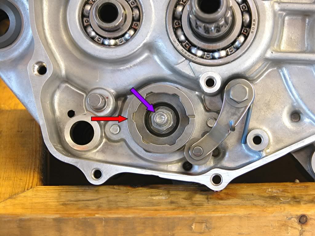
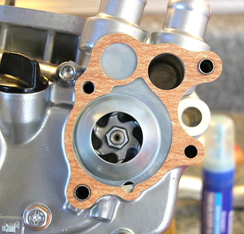
Starting with the right side case, install the bearing retainers
Image
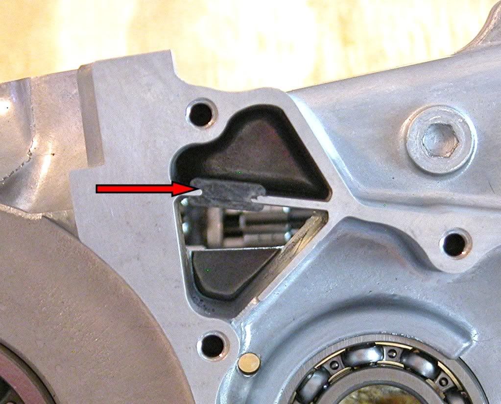
Install the rubber baffle.
Image
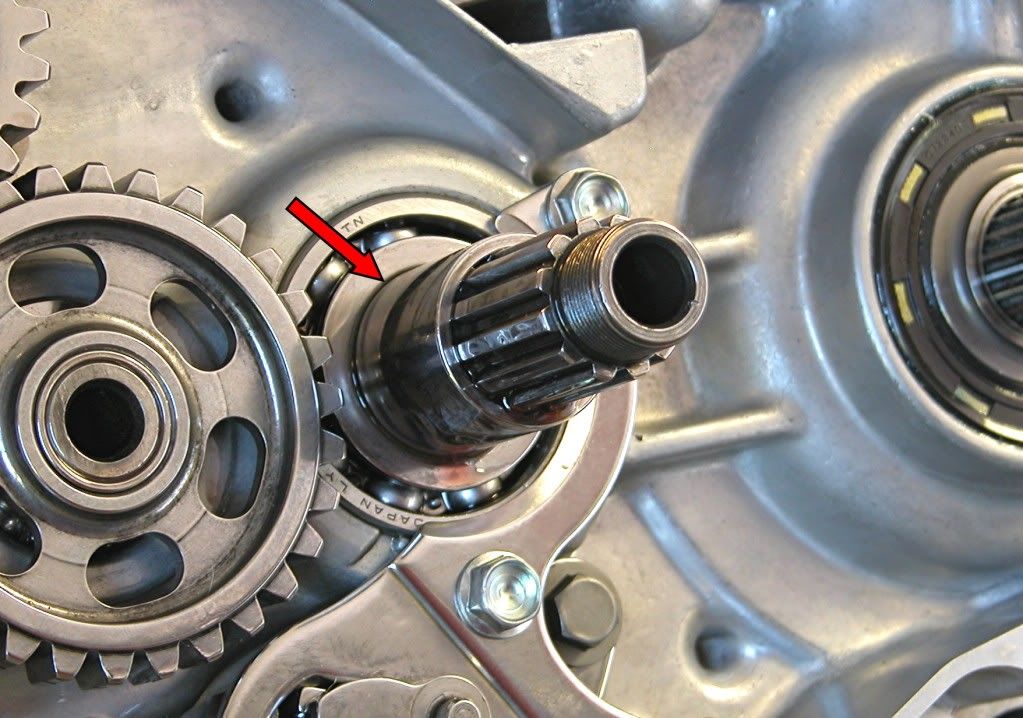
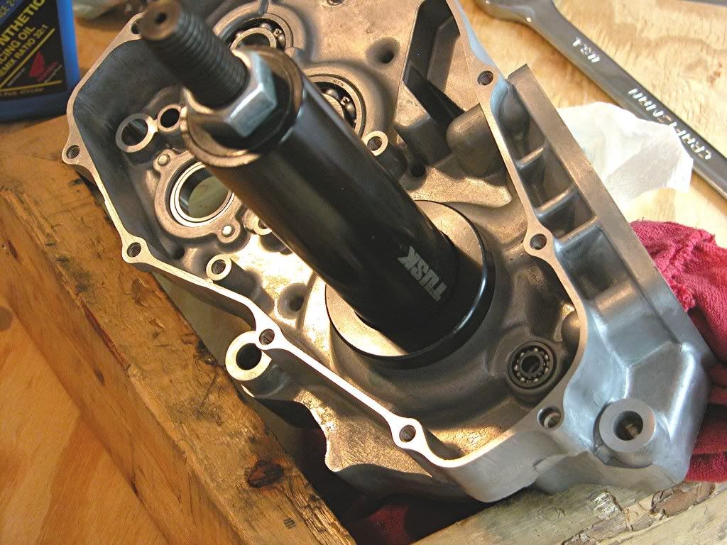
Install the crankshaft in the right side case using a crankshaft installation
tool.
Image
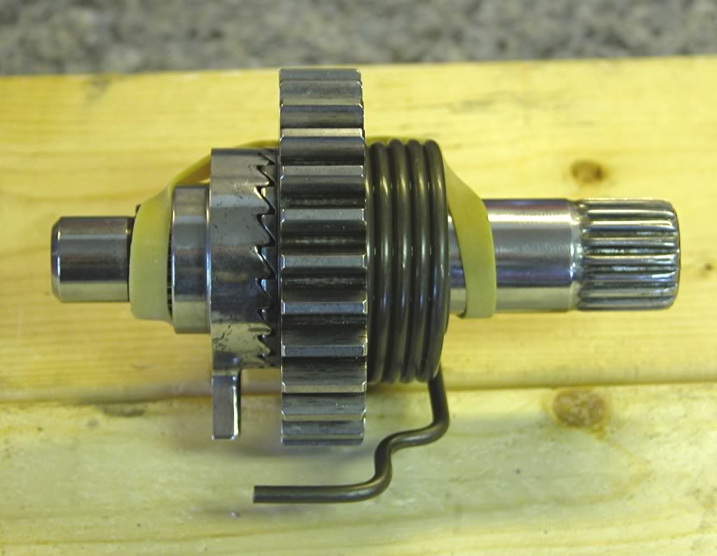
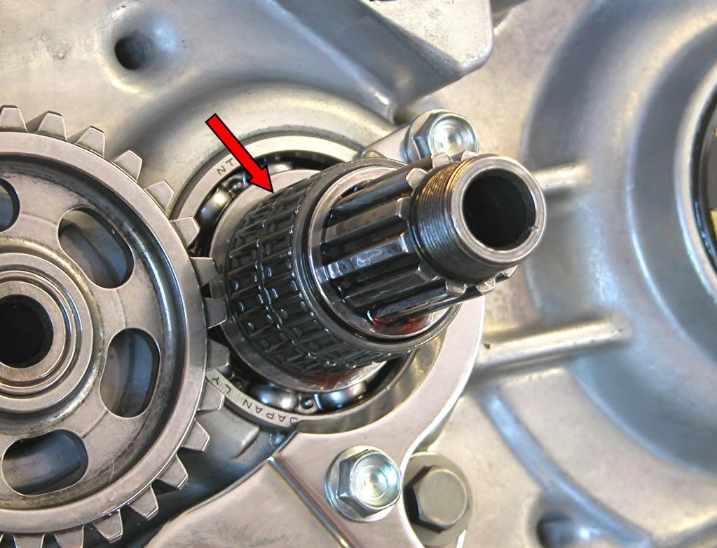
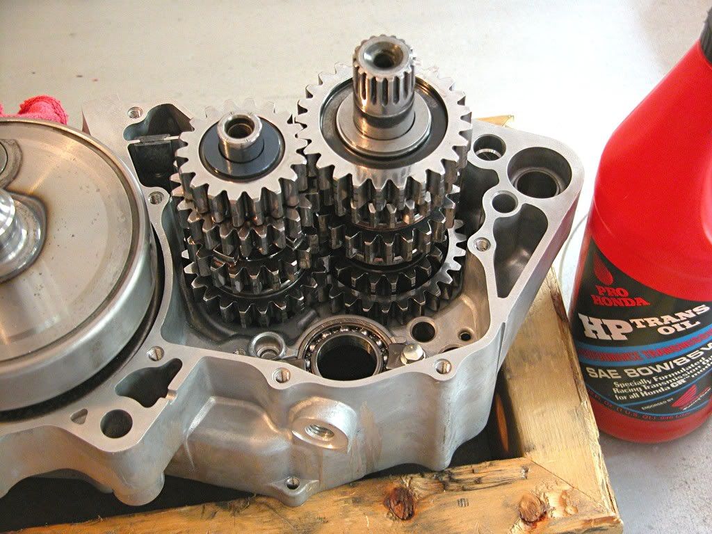
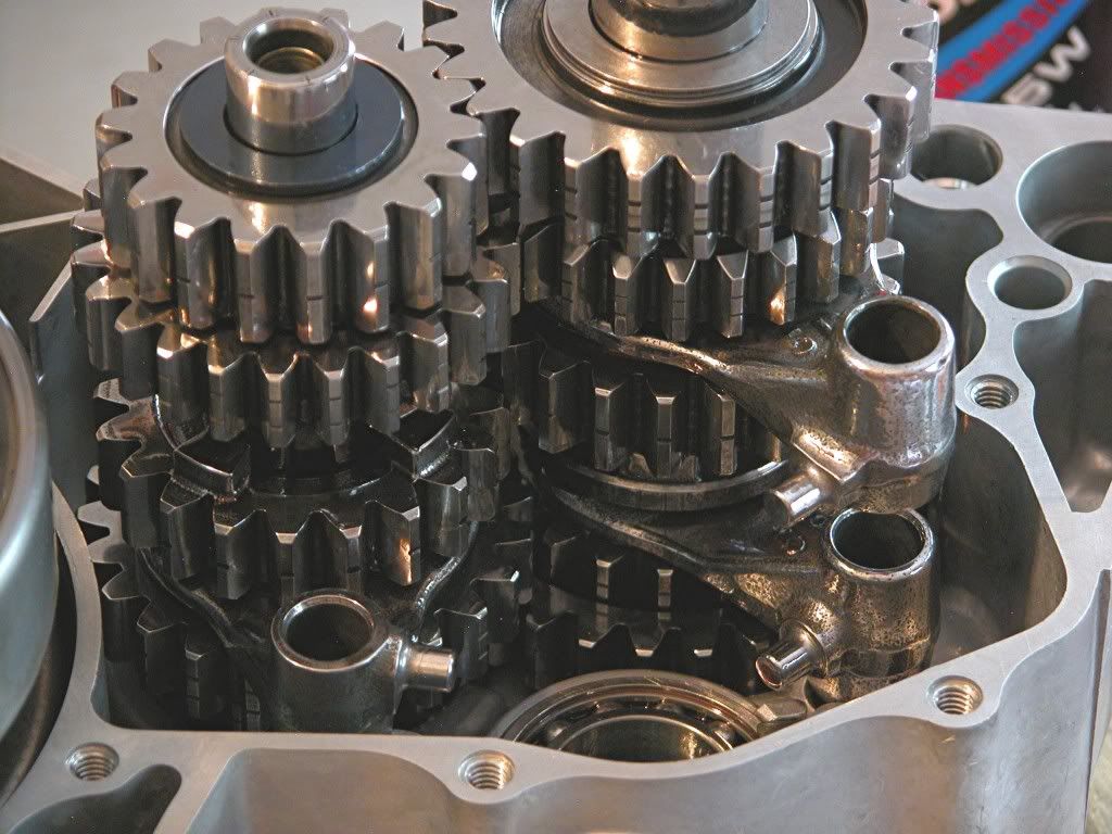
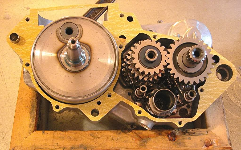
Then install the previously assembled transmission clusters
Image
Image
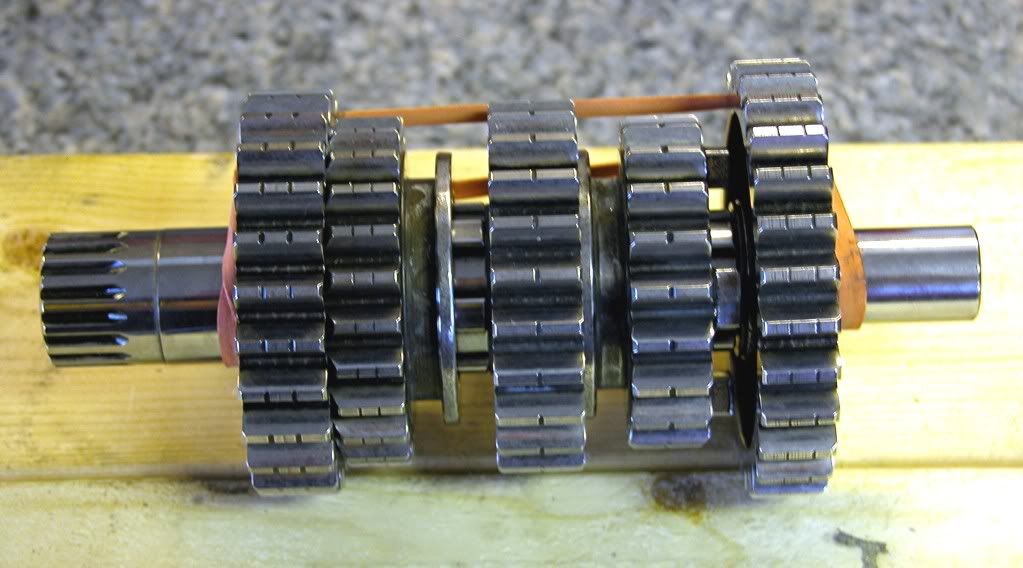
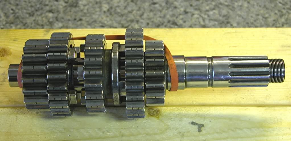
after lubricating with clean gear oil (Honda HP Pro) into the right side case.
The clusters have to be installed meshed together.
Image
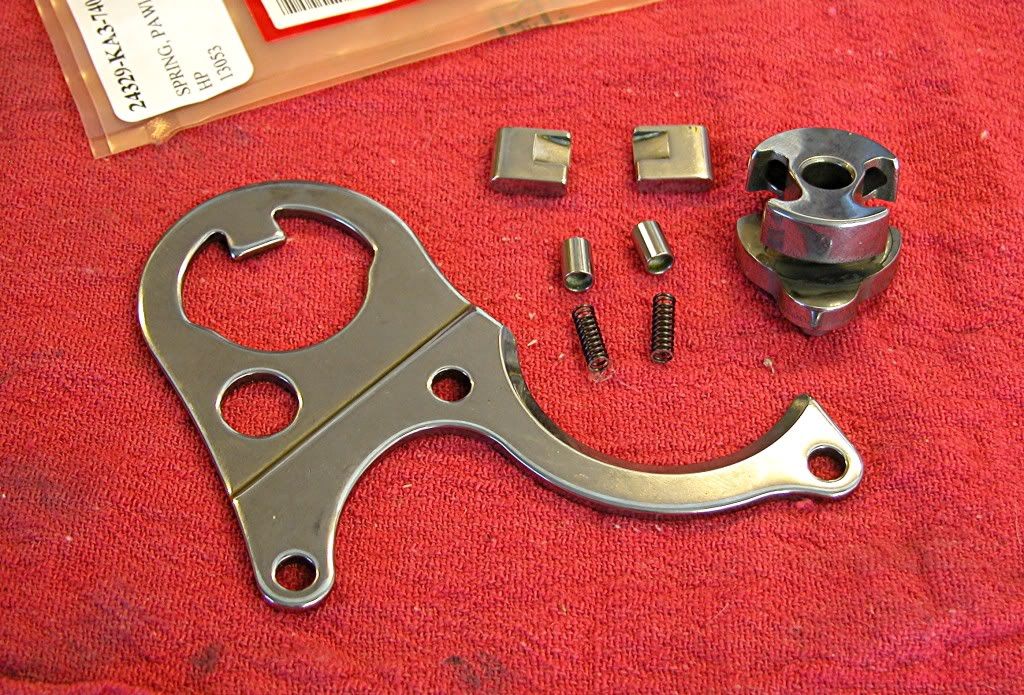
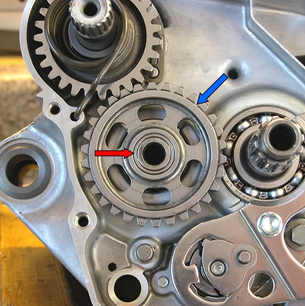
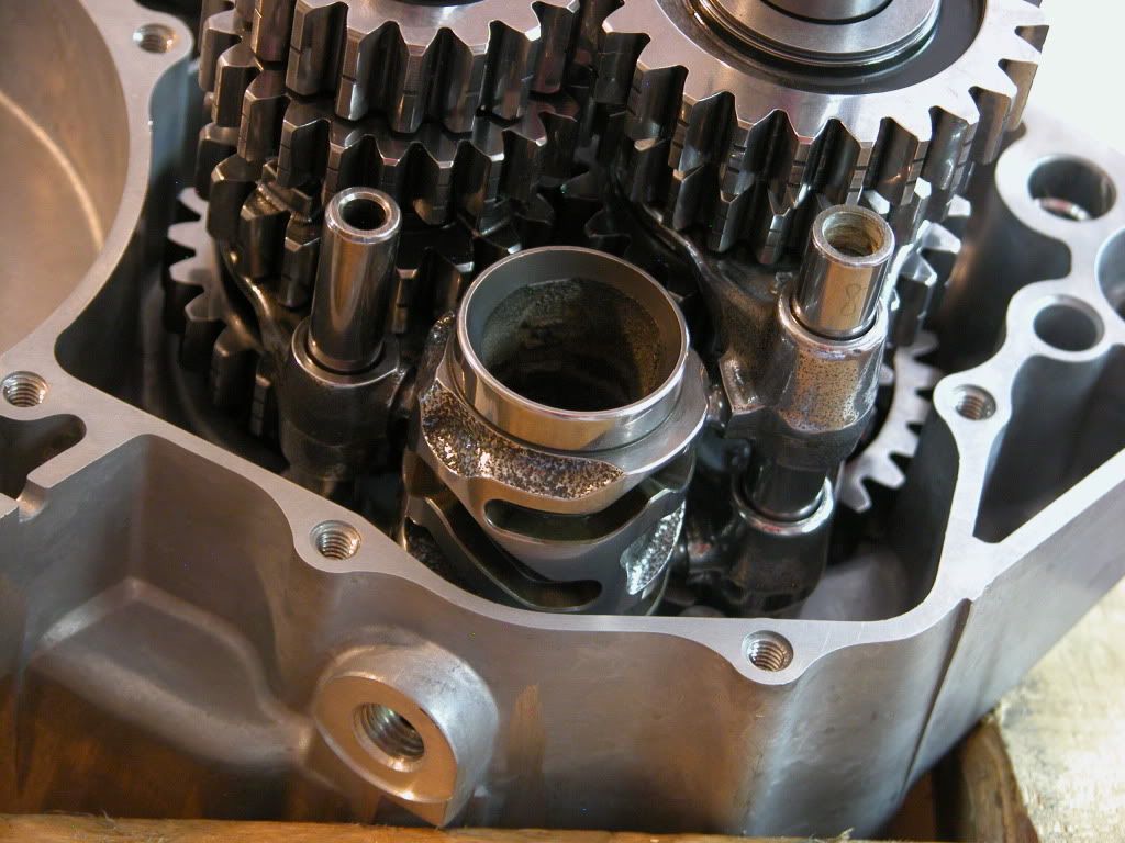
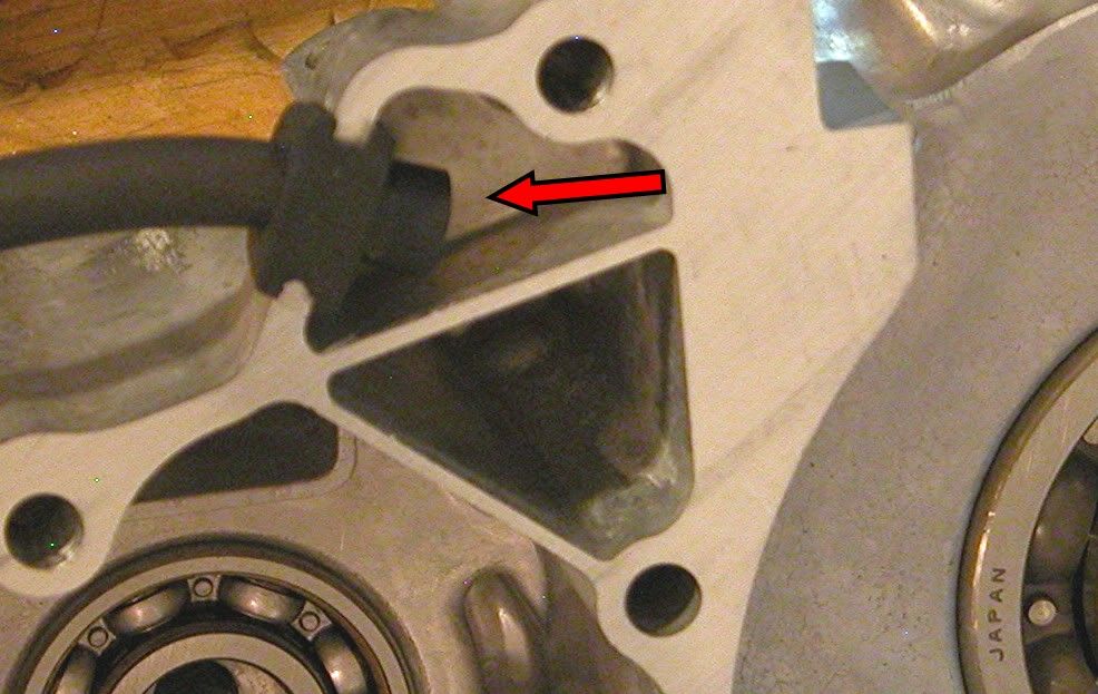
Next up are the shift forks. Forks stamped "R" and "L" on the right
side of the shift drum with "R" on the bottom and the fork stamped
"C" on the left. Douse everything in gear oil before installing
Image
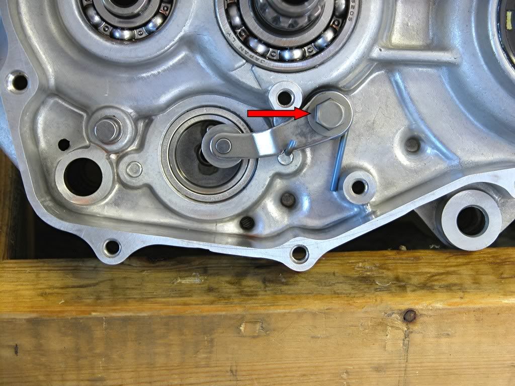
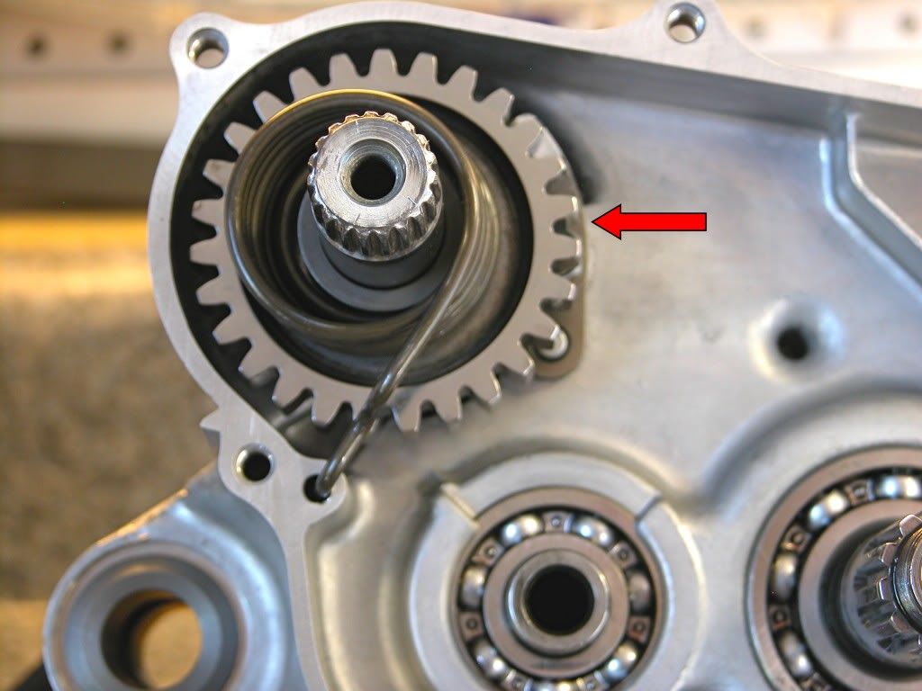
Now install the shift drum after coating it with gear oil. Insert the shift
fork pins into the shift drum grooves.
Image
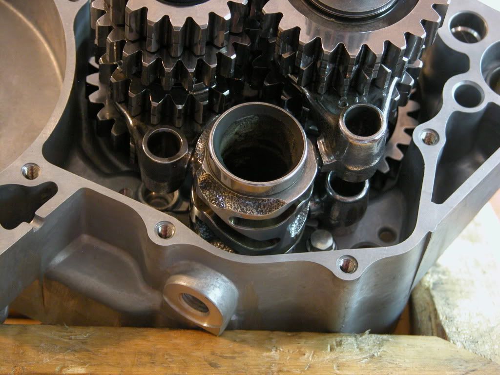
Finally, coat the shift fork shafts with gear oil and install.
Image

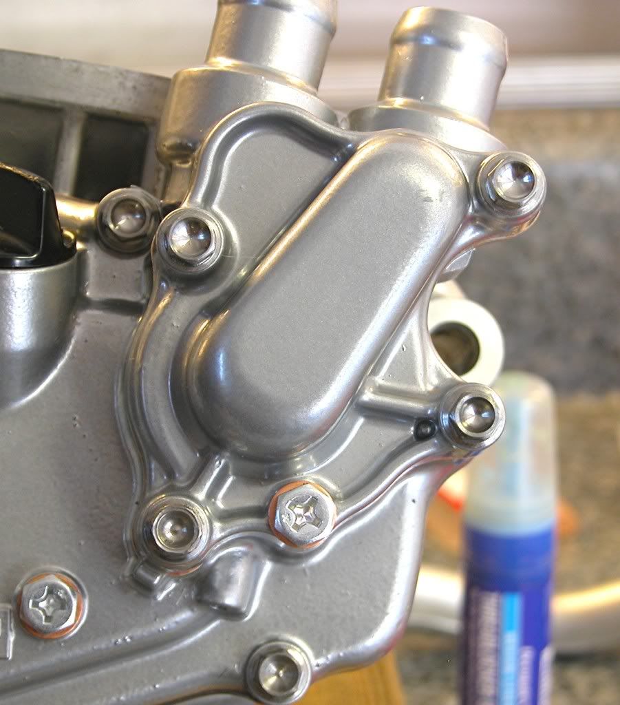
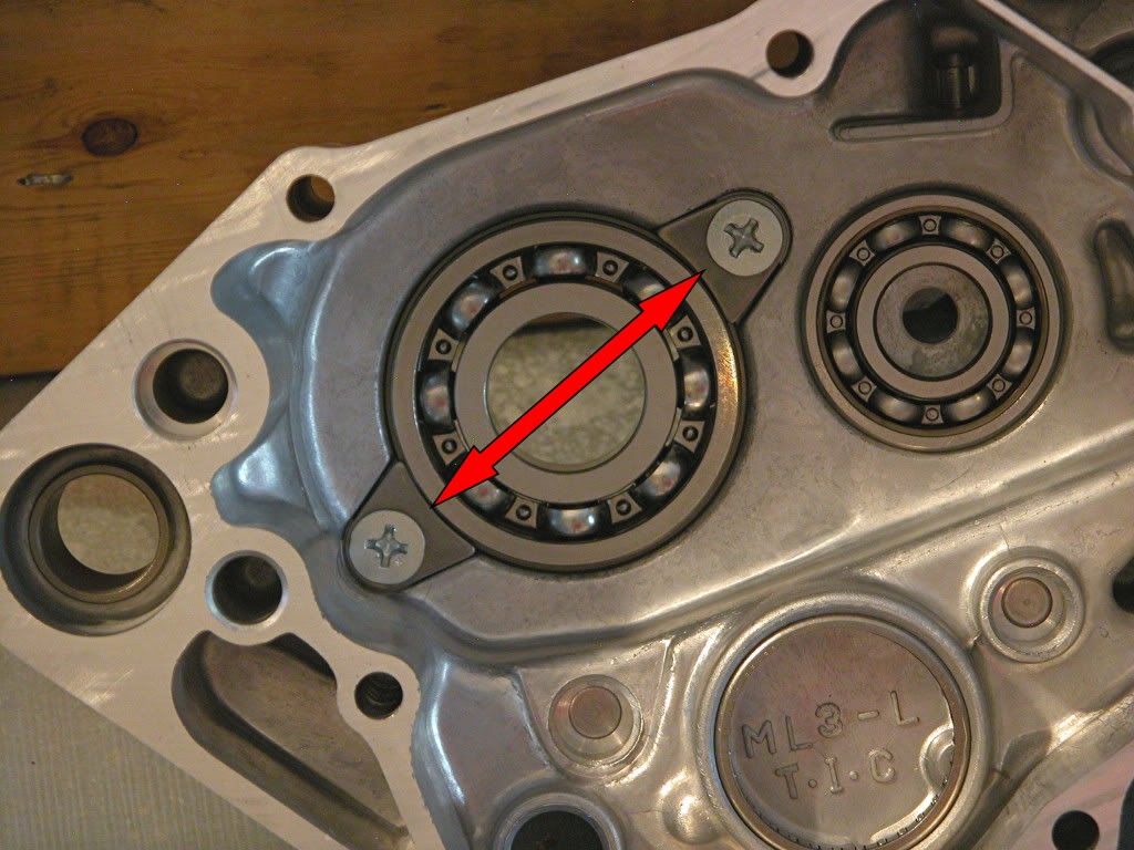
Now turn your attention to the left side case half and install the bearing
retainer as shown using threadlock on the screws and torquing to 7 lb.ft.
Image
install the crankcase ventilation hose.
Image
Back to the right side case, lubricate the two dowels with oil and install
along with a new gasket.
Image
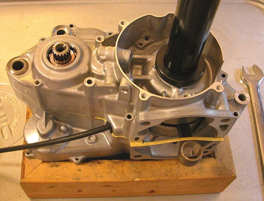
Place the left side case on the right and install using the crankshaft
installation tool as shown to pull the case together while keeping a
constant gap.
Image
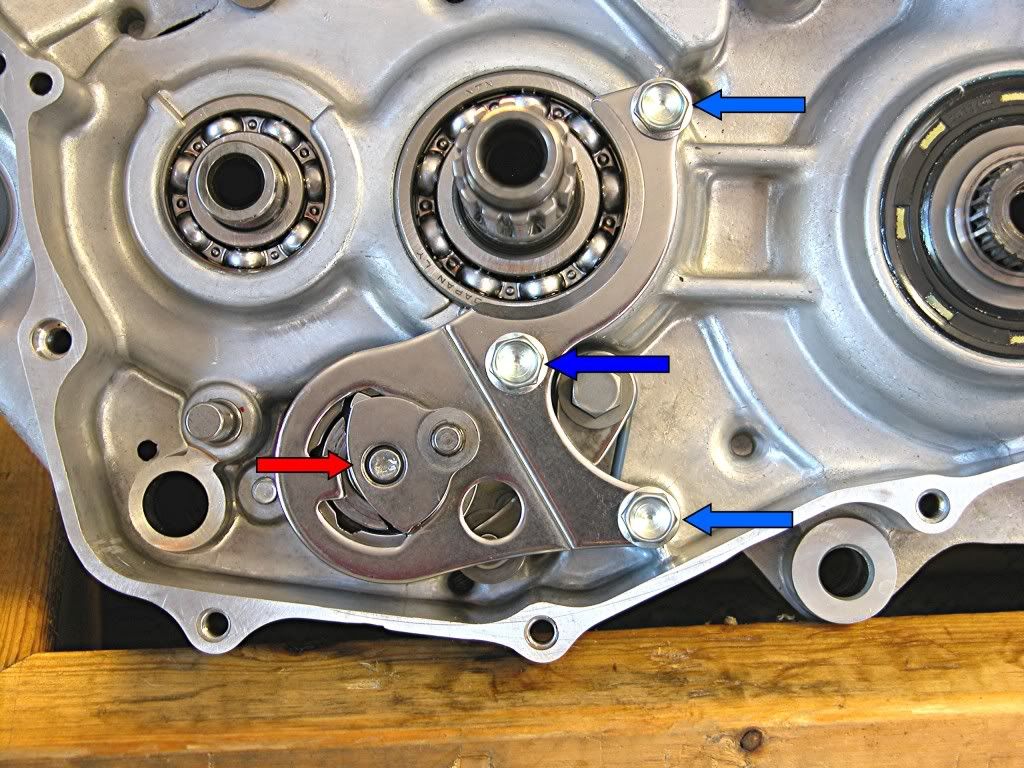
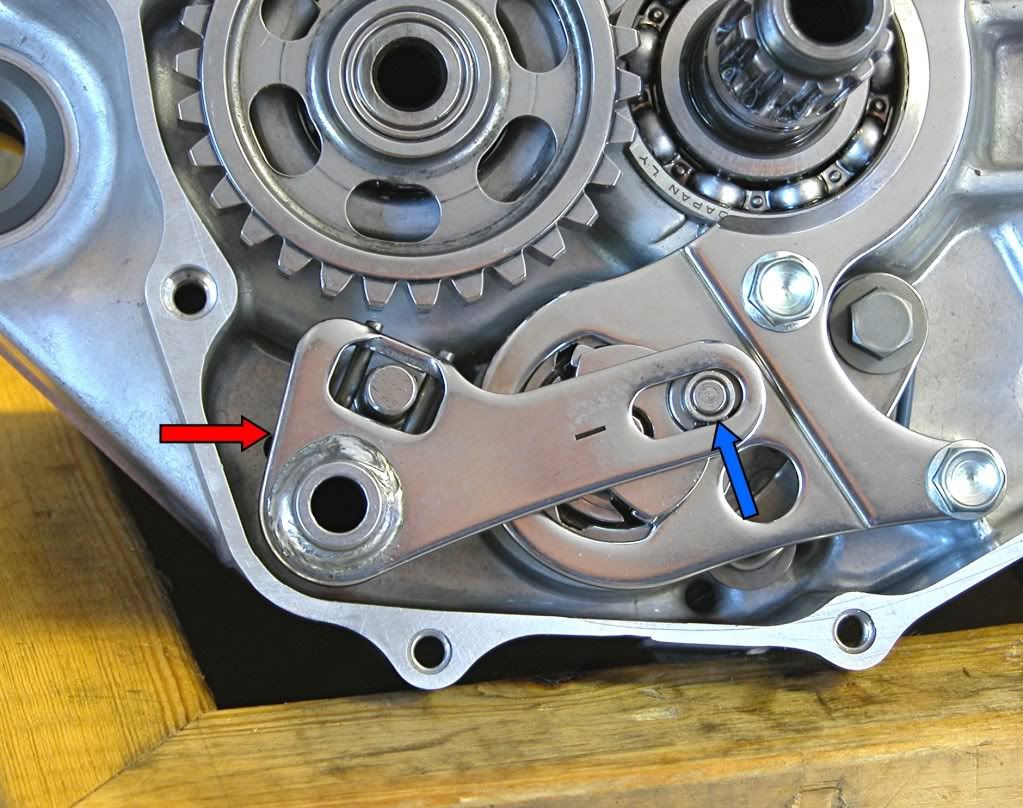
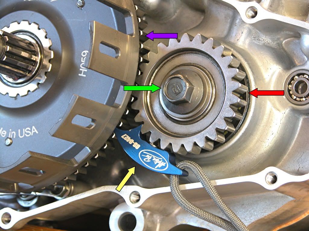
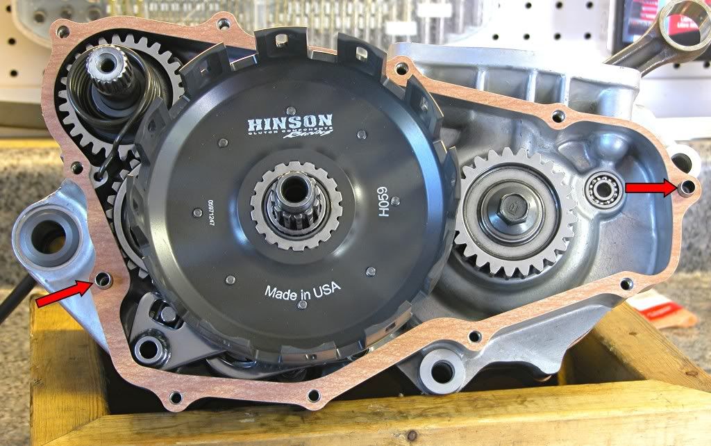
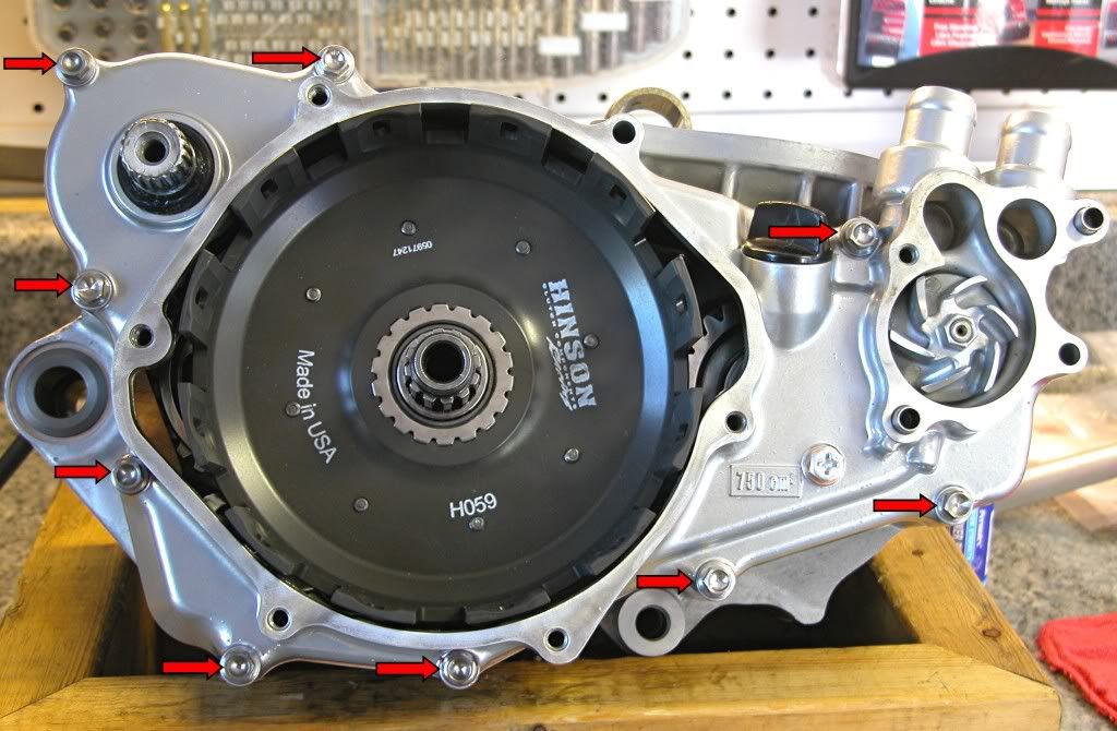
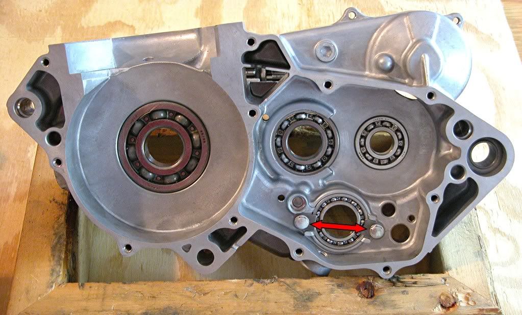
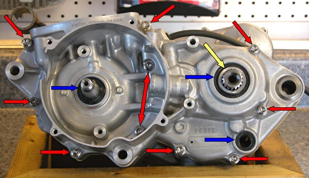
Remove the crankshaft installation tool, install the 10 bolts (Red arrows),
and tighten to 7 lb.ft. Pack the seal lips with grease and install (Blue
arrows). Grease a new O ring and place it in the collar (Yellow arrow)
and install. Don't forget the seal over the clutch actuating rod bore
inside the ignition cavity (not marked). Finally, trim the excess gasket
material above the cylinder deck.
Image
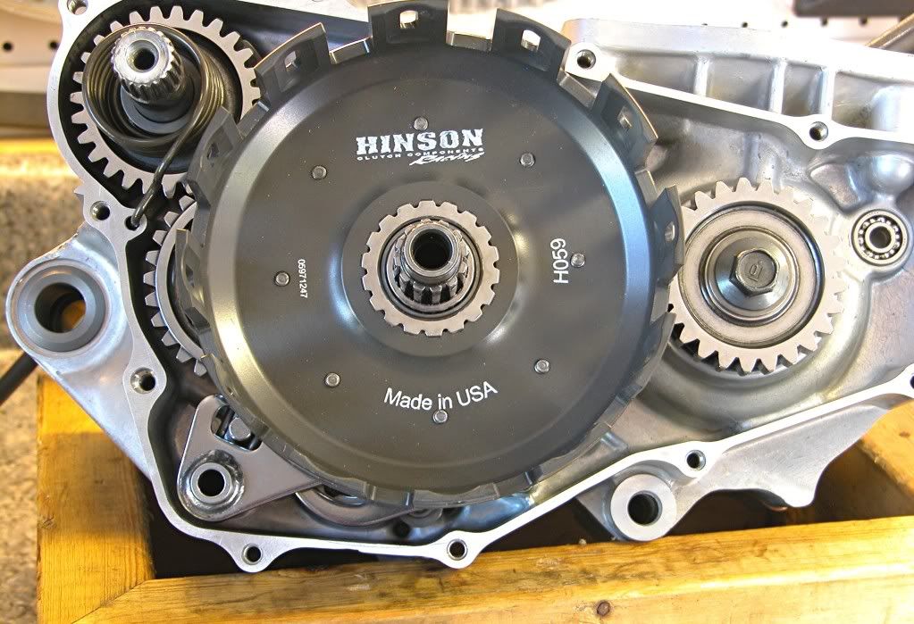
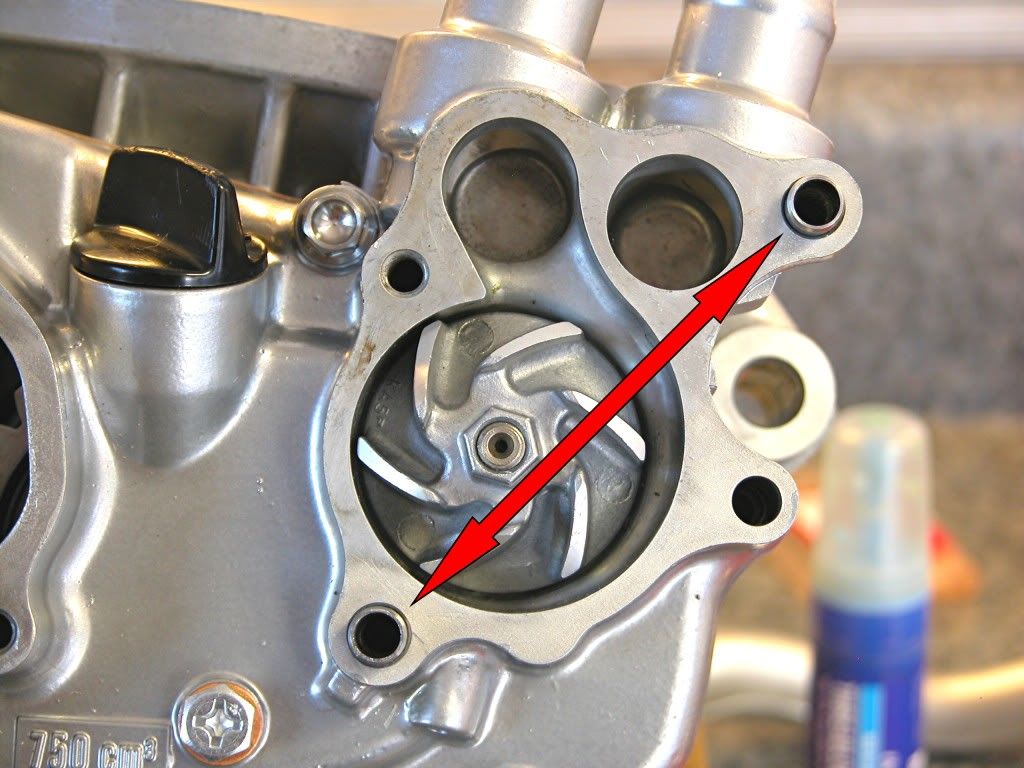
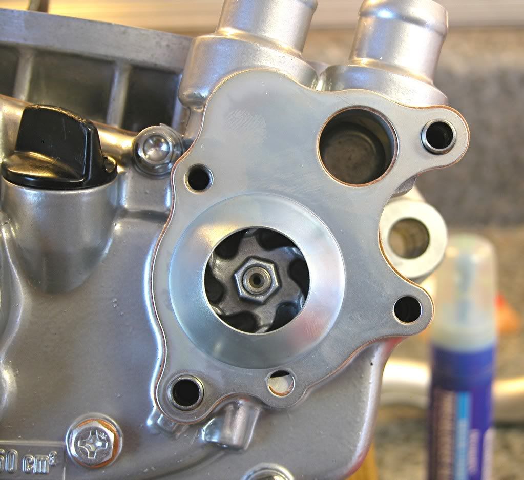
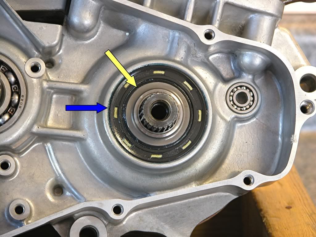
Grease the lips and install a new seal (Blue arrow), and collar (Yellow
arrow), on the right side.
Image

That wraps up this segment. Next up are all the components in the right
side case cover and the ignition.

dogger
User avatar
Tharrell
Posts: 1670
Joined: January 27th, 2010, 11:03 am
Location: Mount Airy, NC

Post by Tharrell »

Sweet!
I hope these become stickies.
User avatar
AlisoBob
"Hoon-father"
Posts: 15404
Joined: May 31st, 2007, 6:39 pm
Location: Aliso Viejo Ca

Post by AlisoBob »

Non OEM center case gasket.....

:nono:
100hp honda
Posts: 4394
Joined: July 4th, 2007, 6:57 pm

Post by 100hp honda »

sweet :cool: . can i add a few things. antiseize on the dowels will make it easy coming apart next time, oil may work the same but ive never tried it so i dont know. becareful how far in you put the seals
User avatar
AlisoBob
"Hoon-father"
Posts: 15404
Joined: May 31st, 2007, 6:39 pm
Location: Aliso Viejo Ca

Post by AlisoBob »

Part 2 from Dogger.....

Now it's time to install all the components on the right side of the
combined cases. When I speak of gear lube, I am using Honda HP
Pro. This is a good lube for assembly and break-in. If you want to
switch to the latest synthetic after break-in, that's your choice.

Start with the neutral stopper arm.
Image
Install the lever and a new spring and washer. Torque the bolt (arrow) to 9 lb.ft.

Assemble the drum shifter components into the guide plate. Coat all the
components with clean gear lube. As I stated previously, these are new
pawls, springs and plungers that should be replaced at every rebuild.
Image
Install guide pin in the shift drum then install the drum center (Red arrow)
while holding the neutral stopper arm back with a screwdriver. Torque the
center pin (purple arrow) to 16 lb.ft.
Image
Set the drum center to a position other than neutral and install the
pre-assembled guide plate with the drum shifter over the center pin (Red
arrow), while holding on to the rachet pawls. Torque the three retaining
bolts (Blue arrows) to 10 lb.ft.
Image

Assemble the kick start assembly as shown.
Image
Place the kick start assembly in the case and wind the new return spring clockwise until the end can be inserted into the case.
Image
Install the idler gear (Blue arrow)and bushing (Red arrow) after coating both with gear oil.
Image
Place the shifter collar on the drum shifter (Blue arrow). Assemble the
gearshift spindle return spring, snap ring and thrust washer and install
straddling the case pin as shown.
Image
Coat the clutch outer guide with gear oils and install.
Image
Coat the needle bearing with gear oil and install.
Image
Install the primary drive gear (Red arrow) and bolt/washer (Green arrow).
Install the clutch outer (Purple Arrow). Place a gear jamming device
(Yellow arrow) between the primary gear and clutch drive gear as shown
and torque the primary drive gear bolt (Green arrow) to 33 lb.ft.
Image
That's everything on the right side.
Image
Oil and install the two dowels (Red arrows) and a new gasket.
Image

Install the right side case cover, torquing the bolts to 7 lb.ft. in several
steps and in a criss cross pattern. If you are using ti bolts, make sure you coat
them with grease or ti prep prior to installation or you may never get them out
in one piece.
Image
Oil and insert the two dowels as shown
Image
Place a new gasket on the water pump housing followed by the separator
plate.
Image
Place a second gasket on the separator plate.
Image

Install the water pump cover and torque the bolts to 9 lb.ft.
Image


That's it for this time. Next, the clutch and ignition.

dogger
Post Reply