combined cases. When I speak of gear lube, I am using Honda HP
Pro. This is a good lube for assembly and break-in. If you want to
switch to the latest synthetic after break-in, that's your choice.
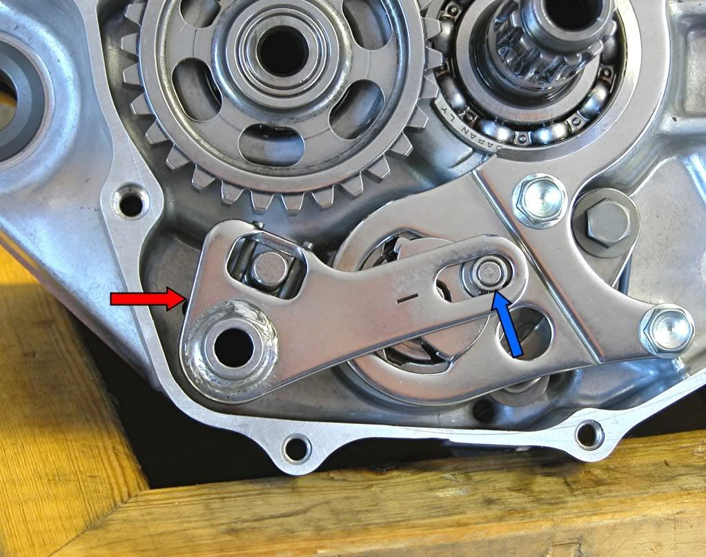
Start with the neutral stopper arm.
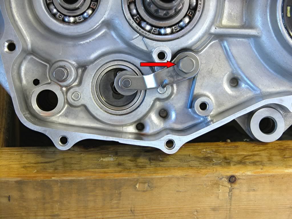
Install the lever and a new spring and washer. Torque the bolt (arrow) to 9 lb.ft.
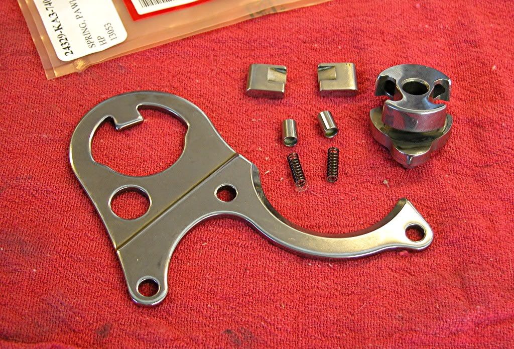
Assemble the drum shifter components into the guide plate. Coat all the
components with clean gear lube. As I stated previously, these are new
pawls, springs and plungers that should be replaced at every rebuild.
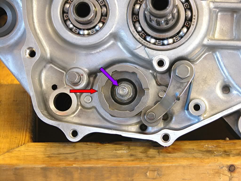
Install guide pin in the shift drum then install the drum center (Red arrow)
while holding the neutral stopper arm back with a screwdriver. Torque the
center pin (purple arrow) to 16 lb.ft.
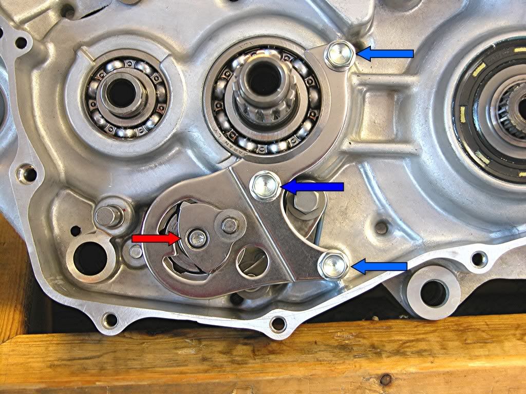
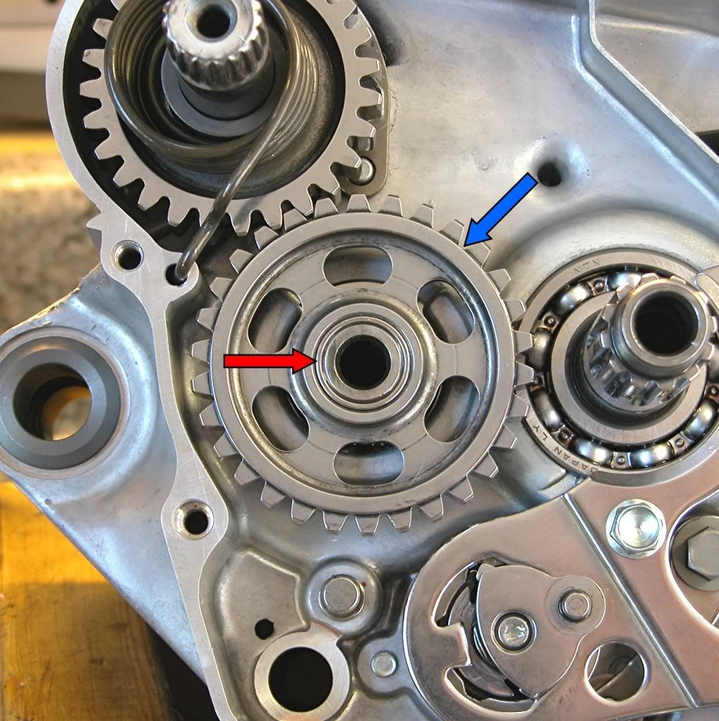
Set the drum center to a position other than neutral and install the
pre-assembled guide plate with the drum shifter over the center pin (Red
arrow), while holding on to the rachet pawls. Torque the three retaining
bolts (Blue arrows) to 10 lb.ft.
Assemble the kick start assembly as shown.
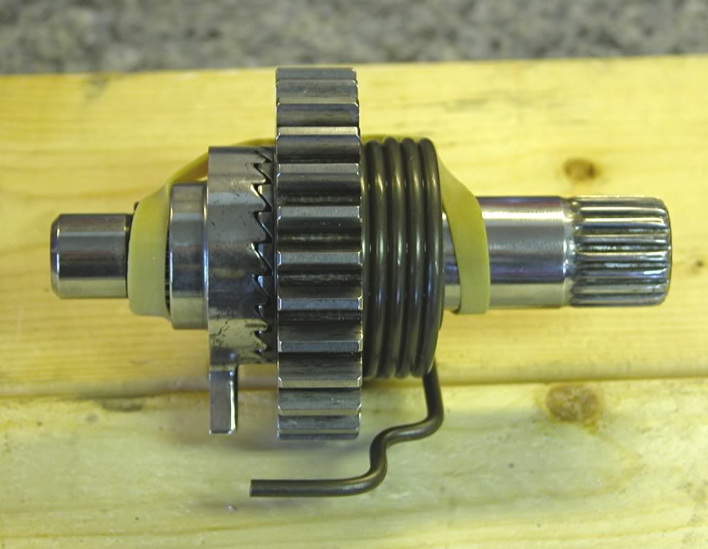
Place the kick start assembly in the case and wind the new return spring clockwise until the end can be inserted into the case.
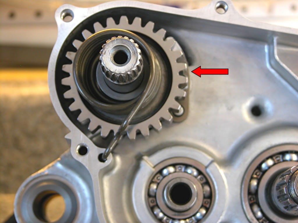
Install the idler gear (Blue arrow)and bushing (Red arrow) after coating both with gear oil.
Place the shifter collar on the drum shifter (Blue arrow). Assemble the
gearshift spindle return spring, snap ring and thrust washer and install
straddling the case pin as shown.
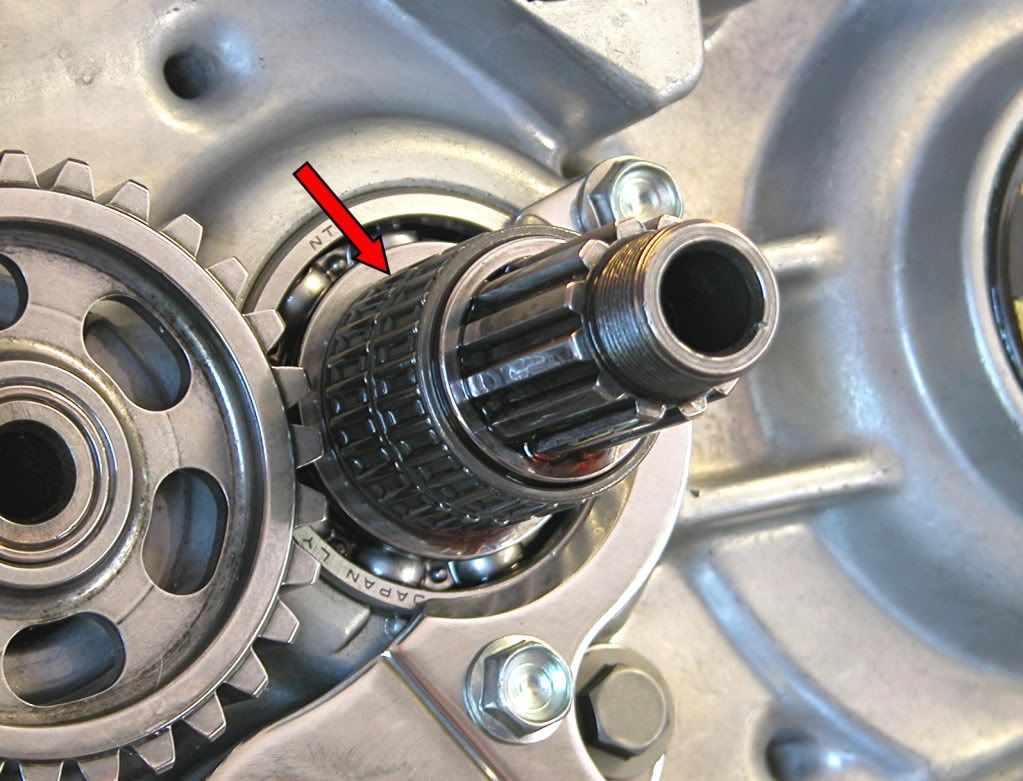
Coat the clutch outer guide with gear oils and install.
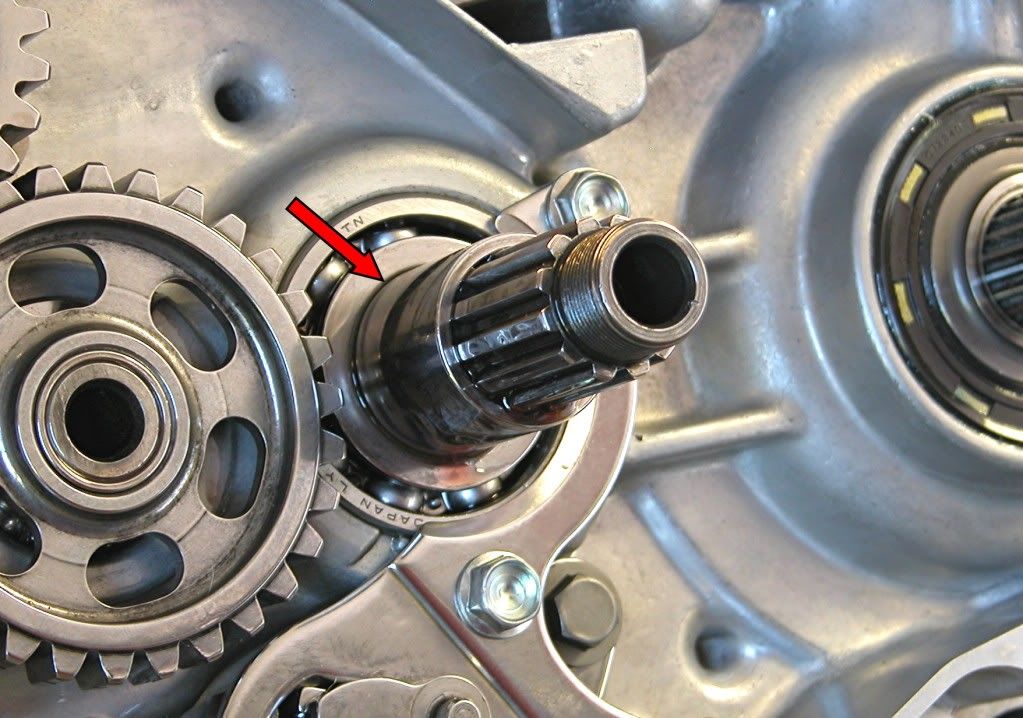
Coat the needle bearing with gear oil and install.
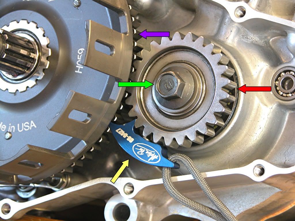
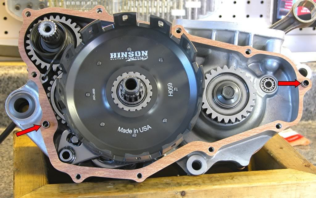
Install the primary drive gear (Red arrow) and bolt/washer (Green arrow).
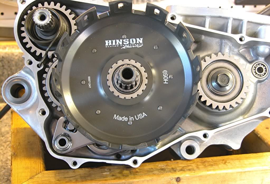
Install the clutch outer (Purple Arrow). Place a gear jamming device
(Yellow arrow) between the primary gear and clutch drive gear as shown
and torque the primary drive gear bolt (Green arrow) to 33 lb.ft.
That's everything on the right side.
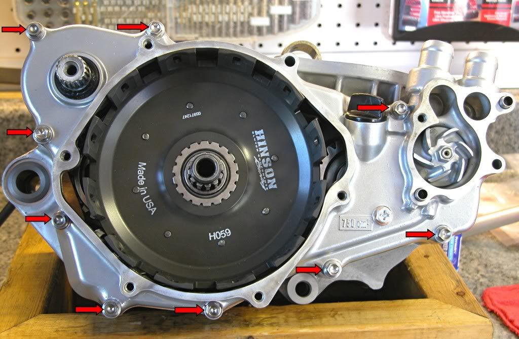
Oil and install the two dowels (Red arrows) and a new gasket.
Install the right side case cover, torquing the bolts to 7 lb.ft. in several
steps and in a criss cross pattern. If you are using ti bolts, make sure you coat
them with grease or ti prep prior to installation or you may never get them out
in one piece.
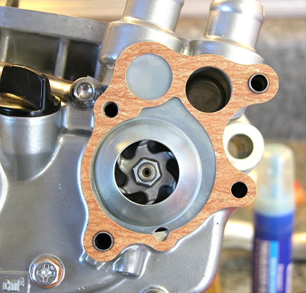
Oil and insert the two dowels as shown
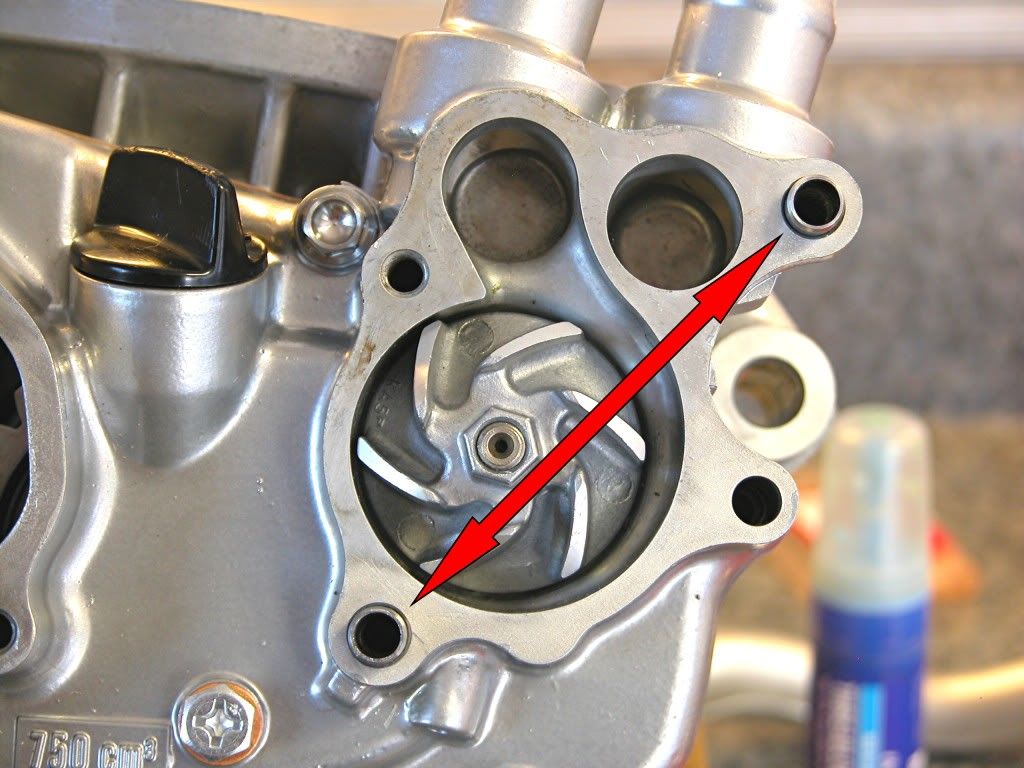
Place a new gasket on the water pump housing followed by the separator
plate.
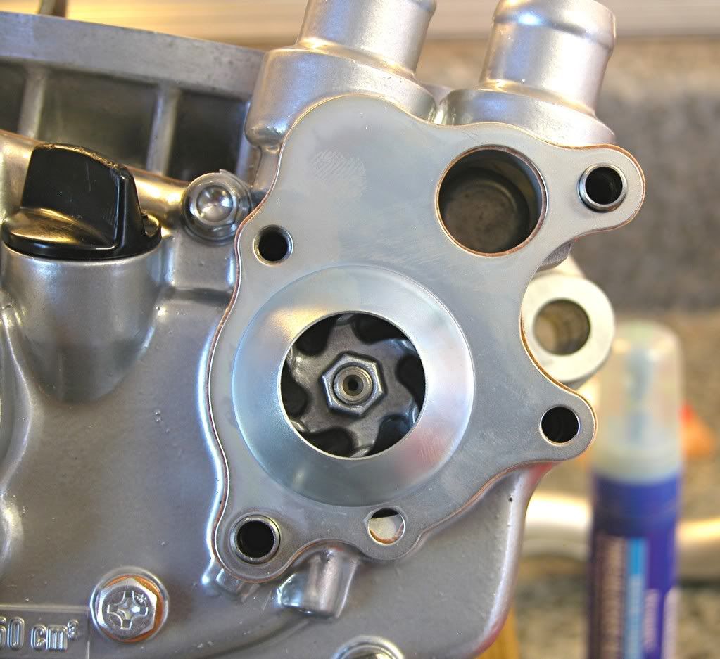
Place a second gasket on the separator plate.
Install the water pump cover and torque the bolts to 9 lb.ft.
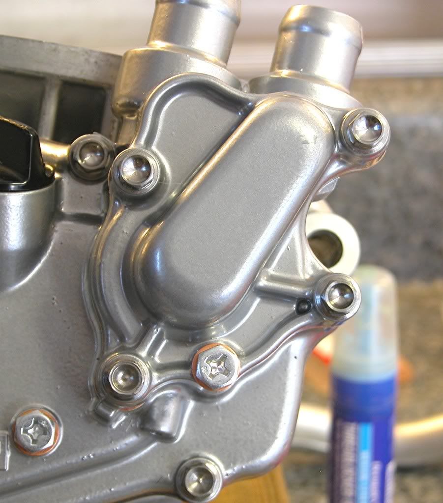
That's it for this time. Next, the clutch and ignition.
dogger